Continue to Site

Welcome to EDAboard.com

Welcome to our site! EDAboard.com is an international Electronics Discussion Forum focused on EDA software, circuits, schematics, books, theory, papers, asic, pld, 8051, DSP, Network, RF, Analog Design, PCB, Service Manuals... and a whole lot more! To participate you need to register. Registration is free. Click here to register now.

What frequency is output pole of buckboost LED driver?

Status
Not open for further replies.
T

treez

Guest
Hello,
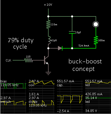
Do you know at what frequency is the output pole of this buckboost led driver?
vin=10
9 leds at 0.5A ~35V
ccm
constant off time
FSW = 119KHZ.

Basso pg 233 says the output pole is wp1 = (vin-2.vout)/(vin-vout) * (1/[RC])

where
C = Cout = 10uF
R = load.......

For the "Load resistance", should i use the dynamic resistance of the LED string, or the quotient V(LEDs)/I(LEDs) ?
 

Attachments

  • Basso 233.pdf
    149.6 KB · Views: 53
  • bukboost.pdf
    33.2 KB · Views: 54

For small signal modeling, you should use the dynamic/small signal resistance of the diode chain + sense resistor as load resistance.
 
  • Like
Reactions: treez

    T

    Points: 2
    Helpful Answer Positive Rating
thanks, though on the 2nd page (LHS) of the following, it says we must use the dynamic resistance of the LEDs plus the V(LEDs)/I(LEDs) quotient....
https://www.ti.com/lit/an/slyt308/slyt308.pdf

...it calls "V(LEDs)/I(LEDs)" the "R(EQ)


Also, please could you advise on whether or not the 3rd equation down on page 233 of the Basso book (attached) is the correct expression for the pole of the output stage of the buckboost here, which is in "constant_off_time" mode.
 

My simulation shows output is always close to 35V and 500 mA.

So you can use V/A as the load resistance. This works only because the smoothing capacitor maintains constant current (more or less).

9643023600_1390586525.png


I observed slow oscillations (maybe 5-20 kHz range) after I changed anything suddenly.
 
  • Like
Reactions: treez

    T

    Points: 2
    Helpful Answer Positive Rating
thanks, though on the 2nd page (LHS) of the following, it says we must use the dynamic resistance of the LEDs plus the V(LEDs)/I(LEDs) quotient....
https://www.ti.com/lit/an/slyt308/slyt308.pdf
I believe that the Req in that paper is present in order to account for the biasing conditions (Vout and Iout), rather than the dynamic behavior of the load. Usually you wouldn't see that represented as a resistance (instead of just Vout/Iout), but mathmatically it works out to be the same.
 
  • Like
Reactions: treez

    T

    Points: 2
    Helpful Answer Positive Rating
OK thanks, I have changed the load "R" value to (9 x 0.6 + 0.8) Ohms = 6.2 Ohms.
As a consequence of this...the feedback loop is now almost impossible to arrange for a good phase and gain margin , when using the equation 2A-22 of the Basso book, page 233.
The plots are as below.
As you can see, the Total loop's magnitude plot has three crossover points.....the compensation components appear conservative, and yet there is dreadful gain and phase margin.
I think that equation 2A-22 cannot be applicable to LED drivers?

Attached please find the buckboost schematic and LTspice simulation
I cannot understand how the simulation is so super-stable when the calculation says it has a terrible gain and phase margin?
I have also attached the gain and phase plots for the Power stage, the Error amp, and the Total Loop.

The Power stage poles for this buckboost LED driver are as follows...
Power stage Pole = 6.1KHz
RHPZ = 1.3KHz
Esr zero = 398KHz.

Do you think its a problem that the RHPZ is a lot below the power stage pole in frequency.?
 

Attachments

  • bukboost.pdf
    33.2 KB · Views: 50
  • bukboost.txt
    9.6 KB · Views: 36
  • Error amp _mag plot.jpg
    Error amp _mag plot.jpg
    44.2 KB · Views: 110
  • Error amp _phase plot.jpg
    Error amp _phase plot.jpg
    41.8 KB · Views: 91
  • Power Stage _Mag plot.jpg
    Power Stage _Mag plot.jpg
    42.4 KB · Views: 83
  • Power stage _phase plot.jpg
    Power stage _phase plot.jpg
    42.2 KB · Views: 87
  • Total Loop _Mag plot.jpg
    Total Loop _Mag plot.jpg
    41.6 KB · Views: 114
  • Total Loop _phase plot.jpg
    Total Loop _phase plot.jpg
    54.2 KB · Views: 87

OK thanks, I have changed the load "R" value to (9 x 0.6 + 0.8) Ohms = 6.2 Ohms.

My quick calculation results in the LED load being 70 ohms avg resistance. (35 / 0.5 )
Because the LED's conduct the same current (more or less), we can consider the value as unchanging.

In this situation the led's work like a resistive load. Practically all of the inductor's output is absorbed by the smoothing capacitor, since it has almost zero resistance.
 
  • Like
Reactions: treez

    T

    Points: 2
    Helpful Answer Positive Rating
Status
Not open for further replies.

Similar threads

Part and Inventory Search

Welcome to EDABoard.com

Sponsor

Back
Top