danishdeshmuk
Advanced Member level 1
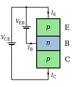
What does it mean by NPN sensor & PNP sensor ?
what's the difference between the two ?
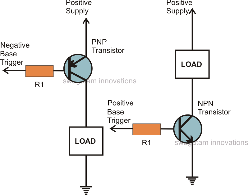
How differently they're used in specific application ?
what's the difference between the two ?
How differently they're used in specific application ?