cupoftea
Advanced Member level 5
Hi,
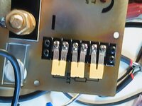
What are these at output of TUNS500 PSU module power supply (attached)
Also, what if S+ and S- are not connected to +vout and -vout.....?.....and you start it up.....will it hit overvoltage and shut down?......or will it literally be damaged?
TUNS500 instruction manual page 7 calls for a 4.7 to 22r resistor as inrush limitation to a HV bus cap of 390-2000uF!....isnt that going to need relay switch out....or be very big. This is a 480W PSU, with vac in of 100-265vac.
Why doesnt it show a schem of the S+/S- connection to vout?
TUNS500F | Product Info. | COSEL Co., Ltd.
Features of TUNS500F. Can see an Item lineup of TUNS500F.
en.cosel.co.jp
Attachments
Last edited: