Continue to Site

Welcome to EDAboard.com

Welcome to our site! EDAboard.com is an international Electronics Discussion Forum focused on EDA software, circuits, schematics, books, theory, papers, asic, pld, 8051, DSP, Network, RF, Analog Design, PCB, Service Manuals... and a whole lot more! To participate you need to register. Registration is free. Click here to register now.

Welder transformer design

Status
Not open for further replies.

salah_edu

Junior Member level 1
Joined
Mar 28, 2008
Messages
17
Helped
0
Reputation
0
Reaction score
0
Trophy points
1,281
Activity points
1,399
Hi All,

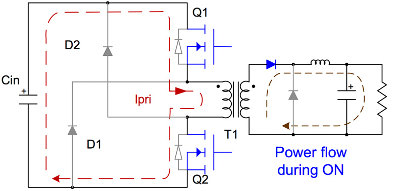
i want to build 5kw welder inverter , so i want to choose a ferrite core for my transformer , the core is a toroid with T63 mm out diameter and 38mm in diameter and 25mm thick and without a gap (MnZn PC40 material), i want to use it in two swich forward converter topology, so is it ok to use this core in this topology wothout a gap , or it must contain a gap ?
Balun-perles-de-ferrite-fil-de-fil-filtre-EMI-anneau-de-ferrite-starter-RF-1ea-lot.jpg_Q90.jpg_.webp
1396624687_Figure%201a.jpg

Thank you
 

respectfully, as I see it, gap does not affect reset time as FvM suggests - reset requires reverse volts for the requisite time, gap = more Imag = faster rise time of reverse volts, but the energy in the Llk is greater, thus the reset time may be longer ...
 

In 2-switch forward, the available reset time is 50 % of the switching period. The criterion for sufficient flux reset is not a certain magnetizung current level but average (DC) flux below saturation margin. That's easier achieved with gapped core.
 

the mag current determines how fast the reset volts rise in the face of device & Tx wdg capacitance - hence a direct effect,

dB/dT = V / ( N . Ae ) notice how there is no relation to flux or effective total mu, the B reached during the on time does not vary with gap ...
 

It's the residual DC flux that varies. Didn't say it's impossible to make forward converter with ungapped core, just a higher risk of core saturation.
--- Updated ---

If you want to make the converter with an ungapped (e.g. ferrite toroid) core, calculate the design. It can surely work, but design tools tell > 100 mm toroid size for a 5 kW forward converter.
 
Last edited:

I was assuming that the magnetizing current won't fall to zero which would relate to a relative large flux in ungapped core. I see however that basic forward converter design instructions, e.g. Lloyd H. Dixon, Transformer and Inductor Design for Optimum Circuit Performance (Unitrode/TI Design Seminar 2002, TI slup205.pdf) are presuming an ungapped core. https://www.ti.com/seclit/ml/slup205/slup205.pdf

Thanks to Easy peasy for insisting in this point.
 

Good thread we've had this one out here before.. i have long been seeking someone to smash my "little gap is good for forwards" postulation...got the threads stored away in the following SMPS course (below).....there were a multitude of points both for and against a gap in a forward core.....and i remember Sunnyskyguy pointing out that an "unlapped, ungapped core set", is actually "gapped" anyway...albeit the gap being tiny.

SMPS course_Big folders
https://drive.google.com/file/d/17ij_pQLkAzzYeL_TRNci86sXHMirKHmD/view?usp=sharing

SMPS course_little folders
https://drive.google.com/file/d/1WvElhDNfHI0EBei4rouSNEdWWTO1oCtJ/view?usp=sharing
 
This thread speaks of gapping a 2 Tran forward core set.....

There are also multiple Power Integrations App notes on 2 Tran Forward where they use a gapped core set.....HyperTFS controller

Page 25 shows the gap in 2 tran fwd core set...
......this never used to be in their app notes....it was added in due to some problem.....and we are lead to believe that it solved that problem.......not saying this means "gap is good for 2 tran forward" though
....pg 27 explains the need for the gap
 

Well, it looks like if there is not enough current on the magnetizing inductance when the mosfets are turned off, the diode from ground to the switching node is not direct polarized, because the current is drawn from the Coos of the mosfets. Then, the node does not reach 0V and so, the bootstrap capacitor is not properly charged.

The ways to deal with it is to gap the core to increase the magnetizing current or to use mosfets with lower Coos.
 
gapping lowers Lmag, raises Imag, which may help in transitions, due to the extra commutation energy

we only gap to help the flux spread more evenly inside the core, usually one layer of Kapton
 
Thanks, the HiperTFS app note calls for gapping as it stops incidences of cycle skipping in light load.....but i cant see whats wrong with cycle skipping in light load?
 

cycle skipping - unless it i well though out can have a deleterious effect on the mosfet that eventually turns on - esp if it is the same one every time and it is a particularly hard switch
 
Status
Not open for further replies.

Similar threads

Part and Inventory Search

Welcome to EDABoard.com

Sponsor

Back
Top