Ioanniss
Newbie

- Joined
- Oct 14, 2013
- Messages
- 3
- Helped
- 0
- Reputation
- 0
- Reaction score
- 0
- Trophy points
- 1,281
- Activity points
- 1,321
Hi all,
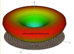
I am trying to get the 3d radiation pattern of a monopole antenna with a rectangle ground plane using HFSS. I expected a radiation pattern like the picture , but I have a pattern exact the same as a dipole antenna.
I dont know why is that, but I thought this happened because I use a ground plane made of vacuum(2 dimenions). I tried to set the PEC material using a 3 dimensional cube for ground plane instead of a 2 dimension rectangle, but the results are still the same.
If you can imagine any explanation I would be grateful!
The parameters I set in ADK are:
frequency: 435 MHz
antenna lenght:17 cm
radius: 0.3445 cm
Feed Gap: 0.3445 cm
Ground plane width: 10cm
Thanks in advance. Any opinion would be very helpful.
Regards
I am trying to get the 3d radiation pattern of a monopole antenna with a rectangle ground plane using HFSS. I expected a radiation pattern like the picture
 , but I have a pattern exact the same as a dipole antenna.
 I dont know why is that, but I thought this happened because I use a ground plane made of vacuum(2 dimenions). I tried to set the PEC material using a 3 dimensional cube for ground plane instead of a 2 dimension rectangle, but the results are still the same.
If you can imagine any explanation I would be grateful!
The parameters I set in ADK are:
frequency: 435 MHz
antenna lenght:17 cm
radius: 0.3445 cm
Feed Gap: 0.3445 cm
Ground plane width: 10cm
Thanks in advance. Any opinion would be very helpful.
Regards


