Continue to Site

Welcome to EDAboard.com

Welcome to our site! EDAboard.com is an international Electronics Discussion Forum focused on EDA software, circuits, schematics, books, theory, papers, asic, pld, 8051, DSP, Network, RF, Analog Design, PCB, Service Manuals... and a whole lot more! To participate you need to register. Registration is free. Click here to register now.

VU Meter Problems Input Source

Status
Not open for further replies.

Linspire

Full Member level 5
Joined
Sep 1, 2011
Messages
303
Helped
1
Reputation
2
Reaction score
1
Trophy points
1,298
Location
M'sia
Activity points
3,279
Hi guys,

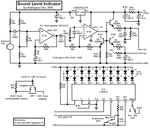
How am I going to get audio input source for VU meter (LM3915)?

I have tried directly connect my 3.5mm jack cable directly to my circuit, it does not work.
 

My VU meter has an electret mic feeding a preamp so its level is good enough for the LM3915 LED driver IC.

Please post your LM3915 schematic. Here is mine:
 

Attachments

  • Sound Level Indicator schematic rev1.PNG
    Sound Level Indicator schematic rev1.PNG
    66.4 KB · Views: 128

The schematics are other people work.not mine.
Here's the schematic attached below,

1.PNG2.PNG

How am I am going to fed the stereo source into the circuit, because I use headphone jack which has left & right channel cable.
 

The circuit should have worked when it was connected to your headphones jack.

The circuit uses an LM386 power amplifier for a preamp instead of using a low noise opamp. It might have too much gain so maybe C2 should be removed.
C1 looks like a polarized 0.47uF electrolytic capacitor. Its value is too high so it rolls off frequencies below 3.4Hz. It should be a 0.22uF film capacitor which will roll off at 7.3Hz.

R4 and R5 set a peak input voltage of 4.4V to turn on the 10th LED but diode D1 messes up this peak voltage requiring it to be 5V. The diode also messes up the range since the first LED should light with an input of 0.2V but instead the bottom 4 LEDs do not light at their expected very low levels (certainly not 20mV).
The diode should be an active peak detector circuit (using an opamp) shown in the datasheet for the LM3915.

A stereo to mono adapter is simply a 10k resistor from the left channel and another 10k resistor from the right channel. Join the outputs of the resistors together at the input of C1. Join the shield of the cable to the circuit's ground.
 

Status
Not open for further replies.

Similar threads

Part and Inventory Search

Welcome to EDABoard.com

Sponsor

Back
Top