Continue to Site
Follow along with the video below to see how to install our site as a web app on your home screen.
Note: This feature may not be available in some browsers.
I used 1uF Tantal capacitor and it worked Thanks once again.
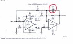
Do I need to use a Tantal capacitor as C2 in the attached image of Precision Rectifier?
can this circuit work or adapted the output of current transformer with a burden resistor
Yes you can use this circuit on the output of current transformer with burden resistor, I have used it upto 2 V
thanks manish.
is the output voltage from the opamp dc
thanks
thank you sir for your quick response..ill be working for a self sustaining charger...
i want it to read the voltage of the battery if it reaches for certain level i want it to switch it to another battery
e.g
volt=adc_read(0)
voltage=(5/1024)*volt
BATTERY1:
if(voltage<3)
{
PORTA=0x01 ; this will activate the Ra0 for relay causing it to switch the battery1 to battery2
volt1=adc_read(1)
voltage1=(5/1024)*volt1
BATTERY2:
if(voltage1<3)
{
PORTA=0x00 ;deactivate the relay on battery1
PORTA=0X02;activate the second relay on Ra1
}
else goto
}
else goto BATTERY1
DO YOU THINK THIS WILL WORK??THANKS in advance
voltage1=(5/1024)*volt1voltage1 = (volt1 * 5) / 1024;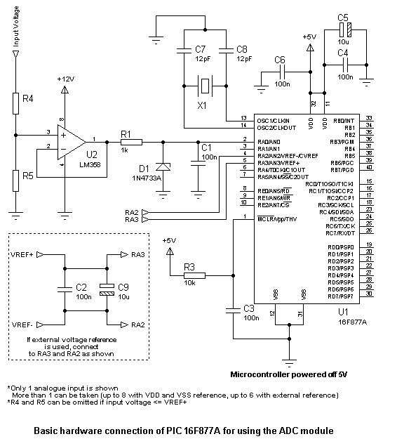
You can find one here on my blog post:
https://www.edaboard.com/blog/1574/
This one:
Before just using the hardware as is, read the blog post. And then decide if the buffer and voltage divider are required.
For clearing ADC-related doubts, go through these:
https://www.edaboard.com/blog/1569/
https://www.edaboard.com/blog/1570/
https://www.edaboard.com/blog/1571/
https://www.edaboard.com/blog/1572/
https://www.edaboard.com/blog/1573/
https://www.edaboard.com/blog/1574/
If, after going through the above, you still have some questions that need to be answered or some doubts that need to be clarified, feel free to ask.
Hope this helps.
Tahmid.
")
You need to step the voltage down so that the 24V is within the 5V maximum. Then, you need to use the PIC to calculate the actual voltage depending on the "scaled" (stepped down) voltage.
need help to making pic16f72 based voltmeter. plz help me..........