Continue to Site

Welcome to EDAboard.com

Welcome to our site! EDAboard.com is an international Electronics Discussion Forum focused on EDA software, circuits, schematics, books, theory, papers, asic, pld, 8051, DSP, Network, RF, Analog Design, PCB, Service Manuals... and a whole lot more! To participate you need to register. Registration is free. Click here to register now.

Voltage Regulator Setlling Time - How to protect supplied electronics?

Status
Not open for further replies.

tonofsteel

Newbie level 4
Joined
May 21, 2013
Messages
5
Helped
0
Reputation
0
Reaction score
0
Trophy points
1,281
Activity points
1,409
20120829_333200.jpg
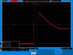
I am using a 3.3 Linear Regulator with a 16VDC supply. The regulator is a LD1086V33. I have powered development boards from this with no problems, BUT it will fry all the XBee's I connect to it. The attached image shows the waveform coming out of the regulator when power is connected. I have tried to measure this about 30 times now and about 1/3 of the time I will see a spike to 8 or 9 volts for 1-4ms before it goes down to 3.3V. The other times it will ramp to 3.3V with no spikes like in the attached image. The XBee will fail after two or three power-ups so I suspect that this voltage spike is wrecking them.

Is this common with all regulators? How do I protect against this? What are common ways of designing power regulator circuit protection for sensitive circuit supplies? I didn't think of checking this out until I had devices failing, is this situation common will all power supplies? If this is true then Digi did a poor job with robust product design.

I was thinking a zener or other diode to clip the voltage past a certain point.

Can a TVS be used for this? I remember seeing that most 3.3V TVS start to turn on above 9V and are made to protect against ESD so this wouldn't work in this case.

How do I build a regulator circuit to avoid these over voltages?
 

This is not normal for linear regulators. Please attach circuit diagram.
 
"Is this common with all regulators?"

No, but it's common with cheaply engineered regulators. Remember that different companies have different engineering philosophies—some companies believe in spending as little time and money developing products as possible, while other companies believe in investing the effort required to make the product right. Invariably, the extra engineering comes with an extra cost.

Providing too much voltage to a circuit can be disastrous. Too much voltage at high current levels, as you've seen, results in the destruction of the components being powered.

If you insist on using this regulator, you might be able to use a large 3.6V zener diode with low series resistance to clamp the output. Otherwise, you might consider using an LM317, or if you really want to spend the money to do it right, a Linear Technology part.
 
I agree with Zeke...No voltage regulator should do this...it is a sure recipe for disaster.

Having said that.....most, if not all LDOs have strict output capacitor requirements.
So, I'm going to ask a silly question: did you check the stability plots in pages 19 and 20 of the datasheet? Does your output cap meet these requirements?
 
You want an input supply that soft-starts, or ramps, at
a rate lower than the dynamic PSRR of the linear regulator
can suppress. There are load switches that provide slew
rate limiting, there are DC-DCs which have soft start
features, all for this (and of course limiting the "slug" to
the upstream supply as well).

Even a LC input filter (properly damped) might do the
job. It looks to me like your bare, bench environment is
just too aggressive for the finite capabilities of your
regulator.
 
Thanks everyone for the suggestions and information, this post stood out in particular based on what I have read in the last few hours:

I agree with Zeke...No voltage regulator should do this...it is a sure recipe for disaster.

Having said that.....most, if not all LDOs have strict output capacitor requirements.
So, I'm going to ask a silly question: did you check the stability plots in pages 19 and 20 of the datasheet? Does your output cap meet these requirements?

I have been reading more about this and I am not even sure that my capacitor does. I did not realize that the capacitor would have that much of an effect on the regulator operation. I will look into this further and do more testing. This also opens up the what happens with age/temp etc variables that will affect the capacitor over time/operation. Most introductions that I have read regarding regulators showed the basic circuit with some emphasis on selecting resistors to set the voltage. Today in addition to your comment I came across more information regarding capacitor properties and their effect on regulator operation.

The circuit is 16VDC in to the regulator with 10uF caps on the input and output on a breadboard. This is connected directly to the VCC pin of the parallax 32400 USB adapter board. I read that this is an acceptable way to power this, but there are variables here that can cause problems. One big one is that the 3.3V regulated output from this regulator circuit I am talking about is feeding into the output of the 32400 on board regulator. I ordered the straight adapter board with nothing other than XBee pin spacing to breadboard pin spacing to avoid these other variables.

With no load on the regulator I did not see these spikes and the spikes would only show up 1/3 of every connection to power.

I did not draft this circuit anywhere as it is 4 parts in total (2 caps, regulator, 32400), so I do not have anything to readily upload. If this cannot be imagined I will try draw something up. I ordered 2 more types of regulators, different caps, straight XBee adapter boards to try get rid of this problem.

As a general question though, how would you protect down stream devices from a regulator? I saw one circuit that used a zener as a voltage reference connected to a comparator which compared this to the voltage supply. The comparator controlled a series pass FET to turn off the voltage downstream if there was an over voltage condition.

I do not see zeners or TVS diodes working on their own since the curves show they dont turn on hard at a specific voltage. The 3.3V TVS could go up to 8V clamping depending on the current.

In case of regulator failure and/or overvoltage how would you protect? Does no-one worry about this since boards are rarely repaired anymore?

- - - Updated - - -

I have LM317 on order and should be here in a day or so, I will look at Linear Technology parts and try some of them. Now that you mention soft start I recall reading some parts that had this (DC-DCs, was staying away from them ATM due to more complexity/part count) I will look into trying out these. LC filter and zener I will also investigate more. I am very interested to see if the zener can hack my circuit into working. I still want to check the capacitors etc to do it right, but I am curious how to overcome "edge case use" after due diligence.

Thanks for the good information and suggestions, I now know where to spend my efforts to learn more about this and how to do it right. Seriously though during prototyping until this setup the regulators *just worked* in the past. I am glad this has happened though because what I am learning from it all. Since this is the first time I had this happen with a regulator circuit I am looking forward to trying different parts/design/analysis and seeing how they make a difference.
 
Last edited:

You are not alone on this issue.

Many moons ago, when SMPS were not as well behaved, I used some ICs called crowbar circuits.
Essentially, they detect an overvoltage condition, and trigger a hefty SCR across the supply's output to short it out and make the fuse blow.
For a semiconductor company to design an IC, surely there is a market for it.

Google the MC3423 or NTE7172 datasheets

You can use your opamp/ zener solution to a similar effect, but crowbar circuits have other features, like prevention from nuisance tripping and indicator outputs.
 

This problem is quite common, it's catching it is the real problem. We were operating unmanned TV transmitters, and occasionally one of the drive PSUs would latch out, so no TV transmission. Turned out that a mains glitch caused the PSU to oscillate on repowering, producing overvoltage, which tripped the SCR crowbar. We had about 200 of these scattered right across the UK, but only a few trips/year. I had to slow down the error amplifier to stop it happening. Took ages to figure out what to do.
Frank
 

Update: I looked into the regulator stability regarding the ESR of the capacitors. My capacitors did not have any readily available spec on ESR (it was electrolytic, so from what I have read it is low) I added 1 and 10 ohms in series with the cap to simulate a higher ESR but the waveform did not change. I tried other capacitors as well and it was the same result.

I setup a variable LM317 and I got the same results no matter what I tried. I am plagued by the waveform shown in the first post, every few times I connect the circuit I get a waveform as shown.

The only way I found to eliminate the problem is to use a 3.3V zener at the output of the regulator (local shop had every value except for 3.6V).

I am still at a loss for what the best practice in this scenario would be?

I am going to look into other solutions and I got more regulators to try out, but if the two I have tried from different series/manufacturers show the exact same response I think there is something else causing this.

Maybe it is even that I am using a 1.5A regulator for a 50mA load? I am thinking if I had this regulator loaded to 750mA there would be much more demand on the output at startup so the initial current draw would keep the voltage from spiking so much. I also need to look into trying a LC filter as mentioned above.

It seems at this point in time though that powering sensitive electronics from a linear regulator for a serious design I would want to have a zener and/or a LC filter to protect from startup spikes and a crowbar to protect against failures from overvoltage.

From this experience I don't think I would design any regulator without these.

I never did check older linear lab power supplies to see what the initial waveform looked like. How did they build these to prevent the initial voltage spike?
 

tonofsteel said:
Maybe it is even that I am using a 1.5A regulator for a 50mA load?

Nope, LM317 shows 50mA is well over the minimum load (5mA according to the datasheet).

Hm, it's funny that nobody shows a turn-on waveform in their datasheets...

Try this chip on for size. At least they show a turn-on waveform.
 

I read Your post again and there are some things that bothers me:
- You wrote that it happens only 1/3 of times. It should happen allways under same circumstances if this behaviour would be property of linear regulator.
- It is very strange that two different regulators behave exactly the same.

Did You test it with different loads? Try to change input voltage. Measure input voltage vaweform.
 

I'll say it again - you need to either include, or require upstream,
a soft start functionality. No old slow regulator can block high
slew rates on the input. More likely you just "wind up" the
error amplifier, to full demand, and get what you show.
 

As a possibility, because you can't get into the error amp, put a darlington transistor across the 3.3V output with the base connected to earth via a 1K resistor*. Now connect this base to the incoming 16V line via a capacitor say 1MF. Now on power up, a fast change of volts on the 16V line will cause the darlington to short out the 3.3V line until the 16V line settles.
* connect a diode across it cathode to base to protect the transistor against reverse Vbe when 16V is switched off.
Frank
 

Status
Not open for further replies.

Similar threads

Part and Inventory Search

Welcome to EDABoard.com

Sponsor

Back
Top