Continue to Site

Welcome to EDAboard.com

Welcome to our site! EDAboard.com is an international Electronics Discussion Forum focused on EDA software, circuits, schematics, books, theory, papers, asic, pld, 8051, DSP, Network, RF, Analog Design, PCB, Service Manuals... and a whole lot more! To participate you need to register. Registration is free. Click here to register now.

Voltage mode controller design for boost converter issue

Status
Not open for further replies.

sabu31

Advanced Member level 1
Joined
Jan 28, 2011
Messages
446
Helped
12
Reputation
24
Reaction score
13
Trophy points
1,298
Activity points
5,153
Hi

I designed a boost converter operating at 50Khz,Vin=100-160V, Vo=400V,Ro=650-2450ohms, L=5mH,C=1mF.
Sensor gain is 1/715(using resistor divider 1M,6.8K given to an opam(voltage follower) and the output is filter throug R-C filter 560ohms,0.22uf and then given to adc channel of micro controller)
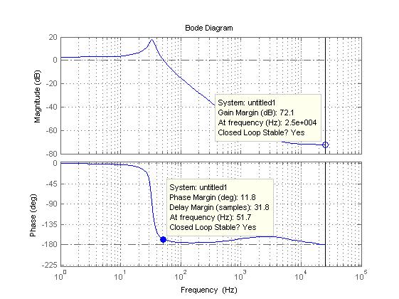
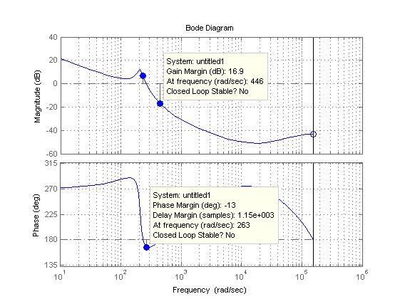
The closed loop controller( discrete) working in Matlab simulink is 16(z-0.99)(z-0.99)/((z-1)*(z-.1)).I am sampling at 2e-5 seconds.. This controller also works in actual hardware using dspic30f2020 microcontroller. Howver the when i check the bode plot of the compensated system, it shows unstable. How is it then working in simulation. If there was a modelling error then hardware and simulation should not match, but in this case ,hardware and simulation is working, but the bode plot is giving opposite answer.

What could be the reason for this.

Thanking you.
 

What are you assuming for the open loop transfer functions of the converter and feedback in simulink?
 

Hi mtweig

Could you clarify what you meant by assumptions. I am assuming ideal switch model,esr 0.1 ohm( i tried without it also). The transfer function of control to output voltage is obtained through state space averaging and then discretized in matlab using c2d function .
 

Ah okay, I had assumed you were using a small signal AC model of a boost converter. If it's something matlab spits out, then I can't really say whether it's valid or not. But it should match up with small signal models found in literature.

So this bode plot, is it generated by the simulation or by the actual hardware? Is it of the closed loop or open loop system? Can you post it?
 

Hi

The transfer function is obtained by writing code in matlab and bode plot is obtained by the bode plot function in matlab. Bode plot is of open loop system. I also compared the transfer function with a paper from TI regarding voltage mode control of boost converter(pg 5) which i have attached. The transfer functions were same . But some how the controller which works in hardware and simulation shows to be unstable in bode plot
 

Attachments

  • voltage mode boost converter.pdf
    1.4 MB · Views: 139

Hi
The transfer function is obtained by writing code in matlab and bode plot is obtained by the bode plot function in matlab. Bode plot is of open loop system. I also compared the transfer function with a paper from TI regarding voltage mode control of boost converter(pg 5) which i have attached. The transfer functions were same .
Okay, so the converter portion itself should have the correct open loop transfer function (but keep in mind the small signal transfer function changes depending on duty cycle, load, etc). That's good.
But some how the controller which works in hardware and simulation shows to be unstable in bode plot
You still haven't clarified what this "unstable" bode plot is actually a bode plot of ("the controller" is incredibly vague) and why you think it's unstable.
 

Hi

The plant transfer function (including sensor gain of 1/715) is

-0.15364 (s-2.597e004) (s+1.111e004)
------------------------------------
(s^2 + 36.71s + 4.449e004)

when discretized using c2d with sampling of 2e-5

-0.15364 (z-1.561) (z-0.7942)
-----------------------------
(z^2 - 1.999z + 0.9993)

The controller tranfer function is
16 (z-0.99)^2
-------------
(z-1) (z-0.1)

This controller works both in matlab-simulink simulation and in actual hardware.But bode plot shows it unstable. The bode plots of plant and compensated system are attached.
 

The first plot of just the converter looks believable. I'm wondering why it doesn't really show a RHP zero though... or is it just close to the LHP zero caused by capacitor ESR? Looks like a fairly difficult system to compensate since the LC resonance is very underdamped.

The second plot looks unstable, definitely. I have to wonder where that huge phase boost above you crossover frequency is, though.

I can think of a couple possible explanations... maybe the gain for the the system is slightly higher or lower than expected, causing the crossover frequency to shift up or down and giving a positive phase margin.

You say it "works" in simulink and matlab simulations, but how are you actually testing it? Transient simulations? If those bode plots are correct, then they can't possibly work properly in a transient simulation (as long as it isn't initialized at steady state). Try and empirically find the crossover frequency and the phase margin of the simulation by inserting a stimulus in the feedback loop, and compare it with the bode plots.

You should also try to empirically measure the loop gain in hardware. This is pretty easy as long as you have a few tools. The method is described here (starts on page 7): https://www.venable.biz/tp-01.pdf
 

Thanks mtwieg for the reply

1) The rhp zero and capacitor esr are fairly close around 2Khz
2)It works in simulink and hardware because i made a closed loop system and i am giving load disturbance from 2450 to 650 ohms and it stabilizes within around 400ms
in hardware and in simulation it takes slightly lesser time.
3) To make the system stable in bode plot i have to give higher gain (100-200) for the controller, however in this case, it works in simulation but in hardware some sort of chattering occurs and it does not stabilize,and the maximum gain i can give in hardware is 256( 8 left shift operations)

Anyways i will check the pdf you have mentioned.

I will check the pdf you have mentioned.
 

Status
Not open for further replies.

Similar threads

Part and Inventory Search

Welcome to EDABoard.com

Sponsor

Back
Top