Continue to Site

Welcome to EDAboard.com

Welcome to our site! EDAboard.com is an international Electronics Discussion Forum focused on EDA software, circuits, schematics, books, theory, papers, asic, pld, 8051, DSP, Network, RF, Analog Design, PCB, Service Manuals... and a whole lot more! To participate you need to register. Registration is free. Click here to register now.

voltage level shifter

Status
Not open for further replies.

casdsys

Newbie level 3
Joined
Aug 13, 2014
Messages
4
Helped
0
Reputation
0
Reaction score
0
Trophy points
1
Activity points
41
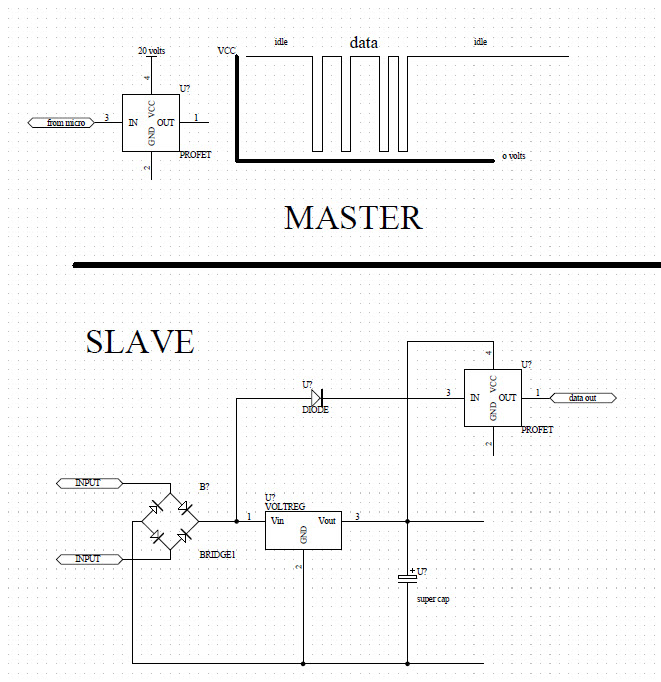
I have data coming out of a device at 5vdc. in order to increase the voltage I can drive a transistor or mosfet with a VCC of my chosing. .i.e having a data line of say 20vdc.

What or how would you make it so I can input data at between 10 - 20vdc and get data at 5vdc ( basically just the reverse of what I started out with ).

Optocoupler perhaps???
 

Hi,

two resistors as voltage divider?

Klaus
 

There are also level shifter from 1,8V to 5V logic levels to 24V and more. Some have 8 channels, like the iC-MFL. To interfacing to industrial levels of 24V see https://www.ichaus.de/wp1_mcu_interface .

Enjpy your design work!
 

Would a 5 volt regulator work or would the response time be too slow.
 

For converting data from 5v to VCC ( 10 to 30 volts ) Iam going to use a profet.
Now to get it back down to 5vdc Im still working on, optocoupler, comparator, something else.......
 

Hi,

it´s not completely clear what you need.

Would a 5 volt regulator work or would the response time be too slow.
No, don´t use a voltage regulator.
It is not built for doing jobs like this. (for sure it may work, but there are more simple solutions)

You didn´t say why the two resistors is no solution...
If you just want to limit a voltage level, then a zener diode is one way.... additionally to the two resistors.

Please show your schematic and give more detailed description.


Klaus
 

Hello Klaus

OK, let me try to explain a little bit of what I hope to achieve.


Lets start with the Master.

I need to send data and power along 2 wires (fig 8 wire) to 1 or many slaves. The master device data is at TTL level but it's connected to a mosfet type device with a VCC of 20vdc, so the data level is between 0-20vdc. The data is actually inverted so when the data is at 0v, the mosfet level is actually at 20vdc. The reason for 20 volts is so if the length of fig 8 cable is 500 metres or more, the voltage drop won't matter because if it's at 10vdc then 10vdc is still considered a "high" compared to zero volts being a low.
The other reason for the inverted data is because I want to avoid using batteries ( rechargeable ) in each of the slaves ( parasitic power )
When there's no data the 20vdc level is used to power up all the slaves.

The slave device.

Has no internal batteries.
Each slave is hooked up in parallel, polarity doesn't matter because of the bridge rectifier.
The 20vdc is used to power a 5v regulator which powers most of the circuitry. There's a super cap of 1 farad to assist when there's data present.
The 20vdc is also connected to a dc - dc step up module to charge up a 10,000uf/25v capacitor at 20vdc.
Even if there is a voltage drop from 20vdc to 10vdc ( really long cable or lots of slaves connected ) the entire electronics will still work.

So of course in the slave I need to reduce the data/VCC line of 10-20vdc to 5vdc
Bi directional data would be nice but I need to try to keep it as simple as possible, so one way data for me will be fine.
There's a bit more to it but this is as simply as I can explain it.
 

For the slave device, a voltage divider would do the voltage conversion. Preferably followed by a ST-gate or a comparator.

You don't necessarily need a supercapacitor to supply the circuit, but a diode + capacitor in fornt of the regulator.
 

Hi,

hope i understood:
Master side: output voltage is 20V DC. (as long as there is no data), OPEN during sending a LOW data bit.
Mind that some PROFET have slow turn ON and turn OFF timing.


****
Btw: with UART idle = HIGH. So UART style data transmission is a good way. With UART 8N1 the worst case is if you transmit "1111 1111" folowed by a stop bit. then you have 9 bit times no power at the slaves.
during this time the capacitor must supply power. (with 2400 baud this means 3.75 ms)
If this is a problem, then check if (inverted) transmission like IrDA does is possible. Then a transmitted HIGH data bit is a short (3/16) low supply pulse and a LOW data is continously on (inverted as IrDA)
(The time the capacitor must supply power now is only 78us @2400 baud
There are UART to IrDa and back pulse transformer ICs)
Then you have at least 13/16 of bit time powered the slaves. With the same baud rate you need only 1/48 of capacitor size. (worst case considerations)
But timing for data is more difficult. see below.
***

Slave:
As FvM mentioned a simple two resistor voltage divider followed by a schmitt trigger should do the job.

But you may need a capacitor at the input of the voltage regulator. But this creates a ow pass filter to your data and transmission may be impossible, because the slave sees no valid LOW voltage level.
To prevent this you have to add one signal diode (1N4148 or similar) from either input ( total 2 diodes) of your "bridge" to the resistor divider.
Especially with long cables you get reasonable cable capacitance again building a low pass filter to you data. Consider using a relativel low ohmic resistor divider.
Try a 750 ohms resistor (it dissipates 250mW at 20V input, so use at least a 0.5W rated) for the upper resistor of the voltage divider and a 330 Ohms for the lower resistor. connect a 3V3 zener in parallel to the 330 Ohms resistor.
Now there shoud be a valid TTL high level for 10V ---20V input and a valid low level for input voltages less than 2.3V.

If the low level is not clean you may consider a half bridge instead of PROFET to actively pull the power line LOW.
Or you may consider a data dectector that refers to supply voltage, built with a comparator.

********
For power saving you may consider a switched mode step down regulator instead of a linear regulator.

Good luck
 

Casdsys,,it appears you are trying to re-invent the wheel.

RS-232 and 488 standards have been around for decades, even DS1 1.54Mbps duo-binary manchester baseband goes for many Km.

What are your data channel requirements and cable restrictions or availability? UTP? CAT3?

Impedance and stray noise matters as well as COMM channel features.
 

There's nothing against designing user specific communication interfaces and protocols for applications. But the intended interface is limited to unidirectional communication which seems a bit inconvenient.

I didn't notice the similarity at first sight, but the M-BUS standard for meter remote reading (EN13757-2) implements a bidirectional communication channel on a similar two-wire connection. https://www.m-bus.com/
 

True enough FVM, There are millions out there, and I've invented my share of power of data links. For improved reliability , however, it is best to learn from the best with, EMC, BER, low cost , ESD and signal integrity over power surges.

What kind of power? 24Vac?
 

Status
Not open for further replies.

Similar threads

Part and Inventory Search

Welcome to EDABoard.com

Sponsor

Back
Top