eduardoAvelar
Newbie level 6
- Joined
- Dec 11, 2017
- Messages
- 11
- Helped
- 0
- Reputation
- 0
- Reaction score
- 0
- Trophy points
- 1
- Location
- MG, Brazil
- Activity points
- 154
Hello everyone!
I am trying to develop a feedback system for my sine wave inverter.
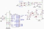
The power is shifted to 12V using a voltage divider, as we can see in the diagram below.
The intention is to use the TL431 together with the 4N25 to isolate the output circuit of the control circuit to maintain safety and prevent interference from switching.
However, the prototype was assembled and results were not expected. When the voltage is less than 12V, the TL431 stops conducting the current and the output voltage of the optical coupler goes to 0V level quickly. When the voltage is greater than or equal to 12V the voltage at the output of the optical coupler goes to 5V.
There is no proportionality of the VFB voltage to the variation at the inverter output.
Could anyone suggest a tip?
Using the TL431 together with the 4N25 to isolate the output is the best solution?
Thank you all.

