Continue to Site

Welcome to EDAboard.com

Welcome to our site! EDAboard.com is an international Electronics Discussion Forum focused on EDA software, circuits, schematics, books, theory, papers, asic, pld, 8051, DSP, Network, RF, Analog Design, PCB, Service Manuals... and a whole lot more! To participate you need to register. Registration is free. Click here to register now.

voltage drop capacitor from mains 230 ac

Status
Not open for further replies.

yassin.kraouch

Advanced Member level 2
Joined
Jul 5, 2009
Messages
631
Helped
40
Reputation
80
Reaction score
40
Trophy points
1,308
Visit site
Activity points
5,094
can you help me to simulate this circuit with ltspice, i want to drive 77 LED from osram
the LED datasheet **broken link removed**
i want to drive the LED at 30 mA,
and i want to use this circuit, i have many error when i tried to simulate the circuit,
i want to simulate output voltage and output current,
 

i want to use this circuit
Where is it?

You may like attaching a screenshot of your LTspice circuit.

For instance, did you hear of:
**broken link removed**
 
Last edited:
  • Like
Reactions: Kral

    Kral

    Points: 2
    Helpful Answer Positive Rating
thanks Karim, i will try agin and upload the schematics, hope that youu and your family are well because of the bad situation in Syria
 

As a small boy I used a series capacitor for a vacuum tube heater. A 12 V heater with 70 mA needed a 1.1 uF capacitor to be connected in series from 220 V AC. For your 30 mA I guess 0.5 uF will be OK. But use only paper capacitors rated to 630 V or more, and add a Zener diode across your LED circuit. I suggest also to add a 100 Ohm, 0.1 W resistor in series as a fuse.
Back then I used German metalized paper capacitors, rated only to 250 V. They often broke down once a second or so, I could hear the clicks. But the heroic RV12 P 2000 tubes survived...
And CAUTION ..Your circuit will be directly connected to 220V mains, therefore all of it VERY DANGEROUS. Enclose it into an insulated box and take care nobody can touch ANY component. LEDS should be covered by a plastic window.
 

When you will upload your circuit (that gives errors hence you couldn't simulate it), we will try removing the cause of each error then analysing it using the appropriate formulas and equations.

Please don't forget giving to each node on your circuit a label. This will ease the discussion/analysis of the circuit.

Obviously, we will also verify how close the calculated results to the ones shown by the simulator are.
 

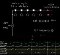
This schematic simulates properly. (In Falstad's simulator.)


Rather than draw 76 led's, I drew only a few. I changed the forward thresholds to a higher amount, so the total adds up to 38 bright white led's at 3.7 V each.

I drew a ground since it is required in some other simulators (although it is not required in Falstads).
 

Status
Not open for further replies.

Part and Inventory Search

Welcome to EDABoard.com

Sponsor

Back
Top