Continue to Site

Welcome to EDAboard.com

Welcome to our site! EDAboard.com is an international Electronics Discussion Forum focused on EDA software, circuits, schematics, books, theory, papers, asic, pld, 8051, DSP, Network, RF, Analog Design, PCB, Service Manuals... and a whole lot more! To participate you need to register. Registration is free. Click here to register now.

voltage converter negative to positive

Status
Not open for further replies.

Gregi

Newbie level 4
Joined
Feb 6, 2013
Messages
5
Helped
0
Reputation
0
Reaction score
0
Trophy points
1,281
Location
Croatia
Activity points
1,320
Hi,
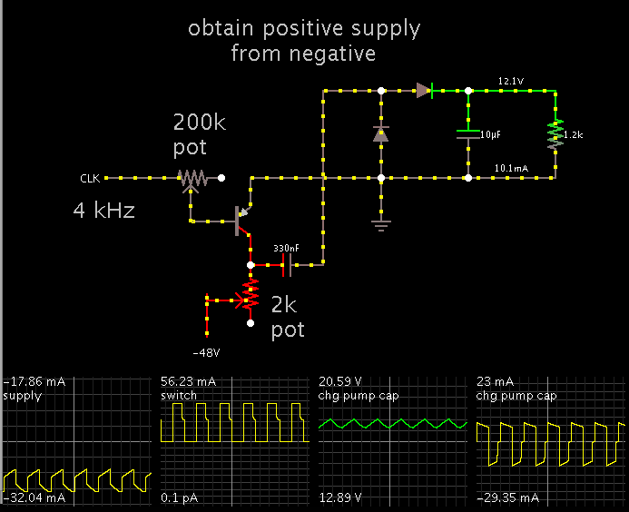
This is one hard question for me but maybe easy answer for someone else. I have power source from public pbx (telephone line) which is -48 volts and 0 volts. Its a Dc voltage. 0 volts is grounded. Is it possible to convert this voltage to positive 12 volts and how. I dont have any ideas.
 

Sure there are ways. But the circuit will need to use the negative supply voltage as its effective ground point (unless you happen to have a separate positive supply available). Depending on the power level, there are many topologies to choose from (flyback and buckboost are suitable for low power).
 

See this thread:
https://www.edaboard.com/threads/41088/

Ringing voltage is around 90VAC and On Hook voltage is 48VDC.


I will not suggest this.

Telecom provider will see that your line drain current for long time, and they can disable your line because inspection and investigation of problem. If you stay around 10-15mA this is ok, but you will get small amout of current.

You can use current in intervals but I see small benefit from all of this and big risk for your phone line.
 

be careful Re:: current drains as drawing more than 25mA renders you as line fault and liable to be cutoff.
Use a flyback converter in the isolation mode and get an opto to control your PWM stabilization.
Input stage needs to use a bridge and a series resistance with relay contacts to open as the ring tone AC voltages of 100VAC exist superposed on the -48VDC used for internal dialling .
 

Its not a problem because telecom is providing me a line for psu. They want to be able to read the temperature inside their systems and i am trying to solve this with arduino and ethernet shield but i have a problem with suplying voltage to arduino (uses 5volts). So they said to me that they can provide me only -48volts and 0 volts grounded. I cant check the link from tpetar right now (my cell phone sucks :) ). Will do it later.

@tpetar imas li skype mozda?
 

I think arduino can draw maximum ~500mA because you can drive arduino with USB port from a PC (500mA max on USB). And I am using arduino UNO R3 board with ATmega 328 but i am still learning how to use it and for the beginer like me its amazing what you can do with it.
 

500mA even in peaks is to much for phone wires. Maybe wires will resist on start but on longer usage for sure some problems will show up.

My thinking is to use some kind of battery/battery pack, and that battery/battery pack can be charger on some other way, like with small solar panel or wall adapter.
 

yeah but.... they told me that they will drive vents with that voltage so dunno how but they will. they will use it for cooling down DSLAM
 

Maybe they do some experimenting, I dont know, but for sure Telecom wires are only good for their designed purpose. Powering something else with higher current over these wires is queasily.

I saw many Telecom centrales analog/newer digital all have one or two big lead acid batteries 100-300Ah, and these batteries are charged over specialized psu or over special dedicated cables from remote location. Power from that battery gives supply for all centrale needs. In main Telecom office can be huge battery bank with big lead acid batteries.


I recommend this book:
Understanding Telephone Electronics
Stephen J. Bigelow, Joseph J. Carr, Steve Winder


I think arduino can draw maximum ~500mA because you can drive arduino with USB port from a PC (500mA max on USB). And I am using arduino UNO R3 board with ATmega 328 but i am still learning how to use it and for the beginer like me its amazing what you can do with it.

Yes Arduino is good but as development board, its not final compact product for some project. Its good for usage in schools or for developing some project, but its not appropriate to embed Arduino in final product. I rather use big development board with lots of capabilities, then working solution goes to first testing PCB, and second modified PCB is final, and all is small and compact. :)


In Off-Hook you should have around 12V.

Check this document:
 

Attachments

  • Analog Telephony Overview.pdf
    199 KB · Views: 216
Last edited:
Typical arduino power draw is 50mA or less. 500mA is the max rating of the on board regulators, but you shouldn't be using anywhere near that. And 50mA from 5V should translate to much less from -48V. I doubt power draw will be an issue.
 

To obtain a positive supply from a negative, using a charge pump:


If more power is needed, then values will need to be adjusted, to allow more current flow in all wires.
 
Gregi for sure if you insist on this power source for Arduino, first make testing in the long run with some other circuit/device such as some LED diode 25mA-35mA or several of them, then if all is ok try Arduino.
 

i dont want that for psu but its othe only thing i get from them :)
so i dont really have a choice :)))
 

Use an ISOLATED flyback topology.

Now, if you are in a hurry and/or you don't have the expertise to design an isolated power supply, you can always purchase a telecom grade power "brick".
Such as this one, its model EC3A32 would do exactly what you require:

https://www.mouser.com/ds/2/75/EC3A-6911.pdf
 

Status
Not open for further replies.

Similar threads

Part and Inventory Search

Welcome to EDABoard.com

Sponsor

Back
Top