Continue to Site

Welcome to EDAboard.com

Welcome to our site! EDAboard.com is an international Electronics Discussion Forum focused on EDA software, circuits, schematics, books, theory, papers, asic, pld, 8051, DSP, Network, RF, Analog Design, PCB, Service Manuals... and a whole lot more! To participate you need to register. Registration is free. Click here to register now.

Voltage controlled variable resister

Status
Not open for further replies.

Audioelegance

Newbie level 4
Newbie level 4
Joined
Mar 25, 2013
Messages
6
Helped
0
Reputation
0
Reaction score
0
Trophy points
1,281
Visit site
Activity points
1,319
I need some assistance in design or someone willing to build. A 0-10vdc input to control a 0-10K resister value. This is to use and analog I/O card on a PLC to control the temperature sensing input to a HVAC unit. Any help would be greatly appreciated.
Thank you,
Zack
 

I need some assistance in design or someone willing to build. A 0-10vdc input to control a 0-10K resister value. This is to use and analog I/O card on a PLC to control the temperature sensing input to a HVAC unit. Any help would be greatly appreciated.
Thank you,
Zack

One of solution can be usage of ADC to measure voltage and based on that voltage result, uC adjust digital potentiometer to corresponding value.
 
Last edited:

It's not clear exactly what you need. :-? Do you want a variable resistor that can be be controlled by the 0-10V input?

Yes, this is exactly what I need.
As far as the use of a digital potentiometer. I need resistance value change that is variable and not stepped as with a digital potentiometer.
Thank you
 

Just to mention that exist digital potentiometer with 1024 steps, in your case if you have 10K its 10R per step, or usage of two with 5K, each 1024 steps, that is 10K/2048 step. :wink:
 

The HVAC unit must be measuring a voltage across the 0-10kOhm resistor. Look for the rest of that circuit, and figure out what the input voltage range is, and just feed it the correct voltage rather than trying to build a voltage controlled resistor.
 

Building a linear voltage controlled resistor is difficult and generally requires a complex circuit. I think Centmo has the correct approach to your problem.
 

Just to mention that exist digital potentiometer with 1024 steps, in your case if you have 10K its 10R per step, or usage of two with 5K, each 1024 steps, that is 10K/2048 step. :wink:

This sounds like a good approach. Is there any who would be willing to build this for me?
 

If you decide to go this route, there is a digital potentiometer IC matching this description on digikey (10kOhm with 1024 steps):

https://www.digikey.ca/product-detail/en/AD5174BRMZ-10/AD5174BRMZ-10-ND/2342495

https://www.analog.com/static/imported-files/data_sheets/AD5174.pdf

...programmable with SPI.

Edit: On further inspection, this part won't work for you since you need to handle 0-10V across the resistor terminals (this one is 5.5V max, 7V absoute max). There may be a way to run two in series but the power supply for the top one gets tricky.
 
Last edited:

You don't say anything about what kind of resistance range you want to cover, what the voltage range is, or how much linearity you need. If you want to stick to analog methods, using a light dependent resistor (LDR) or a JFET might work.
 

input is 0-10 volt DC, to control 0-10K. not exactly linear, but not the end of the world. if a curve could be set up I can supply the curve graph table too.
Anyone willing to build this?
 

When you say 0-10V, are you talking about the control voltage, or the voltage seen by the variable resistor?

Getting all the way down to 0ohms isn't possible, regardless of the method. Even digital pots will usually have >20ohms of wiper resistance which defines an absolute minimum total resistance.
 

Sorry, yes 0-10v control voltage. That is fine, the range that is to be most used will be between 3.5-7k.
 

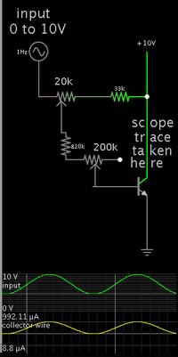
In case this helps...

A transistor acts as a constant current source when the supply is variable...

However if the supply is unchanging then the transistor can act like a variable resistor:


The load would be installed where the collector wire is now.

input is 0-10 volt DC, to control 0-10K

This implies current ranges from 0 to 1 mA. My above schematic provides 1 mA when the input is 10 V.

In case this is not what you are looking for, there are ways to configure transistors in order to obtain the reverse performance.
 

Status
Not open for further replies.

Part and Inventory Search

Welcome to EDABoard.com

Sponsor

Back
Top