Shanjaq
Newbie level 4

- Joined
- Oct 1, 2013
- Messages
- 6
- Helped
- 0
- Reputation
- 0
- Reaction score
- 0
- Trophy points
- 1
- Activity points
- 45
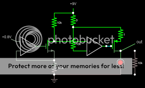
here is the schematic:

and here's the problem:
In the sim, dropping the input voltage to 0 results in an instant cutoff at the output P-FET.
On the breadboard, the output current from the P-FET sloooooooooowly drops to 0 over 5-10 seconds after setting the input/control voltage to 0...
I've build this circuit twice from scratch using different op-amps, same result. I'm using a TLC272 dual op-amp, 2n7000 N-FET and VP0104 P-FET
(supposedly a complement to the 2n7000?)
Why doesn't the second-stage amp drive the gate more forcefully into a cutoff state? I need it to instantly turn on and instantly turn off, or instantly shift to any level in between, as this is for an LED modulator!
Thanks for any help
