Continue to Site

Welcome to EDAboard.com

Welcome to our site! EDAboard.com is an international Electronics Discussion Forum focused on EDA software, circuits, schematics, books, theory, papers, asic, pld, 8051, DSP, Network, RF, Analog Design, PCB, Service Manuals... and a whole lot more! To participate you need to register. Registration is free. Click here to register now.

virtual ground on op-amp?? help needed

Status
Not open for further replies.

PlayaSlaya69

Junior Member level 1
Joined
Aug 17, 2011
Messages
18
Helped
0
Reputation
0
Reaction score
0
Trophy points
1,281
Activity points
1,455
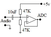
Hi evrybody, i'm planning a project that samples audio signals and then performs some DSP operations on them. However, i first need to amplify the input signal and sample negative amplitude values of the signal as well. Is there any way, or particular component, that could shift the input signal such that there is a virtual ground is at say 2.5 V. This way negative values would occupy the 0-2.5V range, and positive values would occupy the 2.5 - 5V range.

I should mention that my analogue electronics experience isn't very extensive and deally i'd like to keep the solution as simple as possible. So if anyone has any possible ideas or suggestions that i could look into, that would be greatly appreciated...
 

As audio signals don't include DC, AC coupling is usually sufficient to shift the level to the intended 2.5 V.
 

You can use this schematics.


80_1317326112.jpg
 

Thanks bunalmis, your solution seems fairly simple, but would you mind explaining to me whats actually happening in the circuit? Programming is more my thing than analog electronics.
 

Positive input of the opamp have 2.5V DC. The output "ADC" will follow AC from Audio input.
 

In this circuit, the AC signal puts on the 2.5 volts DC. (2.5v is our offset)

ADC input voltage remains within 0 to 5 v if audio signal is max 2.5 vpp.
 

In this circuit, the AC signal puts on the 2.5 volts DC. (2.5v is our offset)

ADC input voltage remains within 0 to 5 v if audio signal is max 2.5 vpp.

I assume you men Vpeak because if Vpp (peak to peak) is 2.5v then the result will be 1.25v to 3.75v (2.5v offset +-1.25v)

Alex
 

Yes, sory I wrong wrote. Max input voltage range is 5v pp.
 

Hi Alex, i built the differential amplifier circuit you suggested, using Rf as 15K and R1 as 10K, with a potential divider circuit providing the 2.5 V bias that goes to the non-inverting pin. It appears to be doing the voltage division, however the output never exceeds 3.7V, shouldn't the maximum be 5V if the op-amp is on a dual 5V and -5V power supply? Also when measured, the voltage at the bias point of the potential divider circuit is 2V rather than 2.5V, is this expected?
 

Yes i have, its an LM324, if thats of any importance
 

No, this is not a rail to rail opamp, and I think it is the reason for the Vcc-1.3v that you mention.
A rail to rail opamp will be able to output 5v with 5v supply while a non rail to rail like the one you use can output a lower voltage than the supply.

You mentioned symmetric power supply, why did you use -5v to the opamp?
 

Oh thankyou, my apologies, I thought it was rail to rail. Can you suggest any common rail to rail op amps I could use? Is the 741 rail to rail? I was just using the symettric power supplies when testing but I realized the -vcc should be grounded.
 

Status
Not open for further replies.

Similar threads

Part and Inventory Search

Welcome to EDABoard.com

Sponsor

Back
Top