Continue to Site

Welcome to EDAboard.com

Welcome to our site! EDAboard.com is an international Electronics Discussion Forum focused on EDA software, circuits, schematics, books, theory, papers, asic, pld, 8051, DSP, Network, RF, Analog Design, PCB, Service Manuals... and a whole lot more! To participate you need to register. Registration is free. Click here to register now.

VA rating of mains transformer for 24W real power output

Status
Not open for further replies.

cupoftea

Advanced Member level 5
Joined
Jun 13, 2021
Messages
2,621
Helped
54
Reputation
108
Reaction score
116
Trophy points
63
Activity points
13,741
Hi,

We want a 50Hz, 240VAC mains transformer to supply 24V at 1A
We therefore selected the following 50VA transformer (504246)

https://docs.rs-online.com/c4ae/0900766b816919e8.pdf
its spec’d for 230VAC and 2*9V sec

However, the VA rating needed depends on the magnetising inductance, which depends on the primary inductance. However, the primary inductance isn’t stated for the above transformer.
So how can we work out if the VA rating is enough for the output power required?

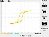
I mean, if you observe the attached, then the transformer with a primary inductance of just 200mH ends up having a power factor of just 0.03. As such, it needs a VA rating of 860VA to supply the 24W output.

LTspice and PDF schem attached.
.....____
A mains transformer based solution has far better mains transient withstand than an offtheshelf SMPS. Also, it is far less EMC noisy. Also, it allows you to select your own electrolytic smoothing capacitors, and so you can select loads of really high quality 125degC ones, and so have really low ripple current in each cap, which means the product will last for decades.
 

Attachments

  • mains transformer.zip
    1.1 KB · Views: 88
  • Mains transformer.pdf
    157.9 KB · Views: 101
Last edited:

Thankyou for that...great points, thats very interesting and worth looking in to....
If i have a 50Hz iron transformer with enough turns to give Lpri = 10H.....then say i reduce the turns (on the same core) such that Lpri now becomes 200mH. Then are we saying that putting it across the mains 240VAC again would now result in B(sat) being exceeded, and also "delta B" being pushed up to a point that the core loss grew much higher?

(Note, when the turns were reduced, lets pretend that the wire diameter was increased such that winding loss remained the same, as when Lpri was 10H)

Do we say that Ferrite is "linear" in that the B by H curve is a straight line up until almost saturation?
However, 50Hz iron core material is "non linear", and its B vs H curve is not ever straight?(unless of course looking over a vanishingly small section)
It's much worse than you think. If you had a transformer with Lpri = 10H, rewinding with HALF the turns would reduce Lpri to 2.5H, and the core would be pushed so far into saturation that the unloaded (but energized) exciting current would be so large that the transformer would likely catch on fire (if the circuit breaker didn't pop!). The non-linearity induced by saturation is strong, and the increase in exciting current due to moving well into saturation is more than one might think. To see this, use a variac to increase the applied primary voltage and watch how fast the current rises. If you were to connect a 50 VA, 115 VAC rated transformer to a 230 VAC source, this would be equivalent to halving the primary turns. The current would be so large that it would likely pop the house circuit breaker for that circuit.

If you had so few turns that Lpri were only .2H, and if you increased the wire diameter to avoid melting the winding due to the massively increased current, you would have created an induction heater:
and the core would melt.

The small transformers sold in ordinary commerce have the primary turns selected to run the core slightly into saturation. Here is the measured hysteresis loop of a small laminated iron core transformer. This is the actual hysteresis loop traversed by this transformer and you can see that the core is pushed into saturation. The smaller the transformer, the further the core is pushed into saturation (by design); this is why very small transformers run hot even when they are unloaded:

TEK0143.jpg
 

Attachments

  • TEK0143.jpg
    TEK0143.jpg
    9 KB · Views: 79
Last edited:
Common, medium loss, silicon transformer steel is somewhat linear up to about 0.8 Tesla, after that the Ur tends to bend over, reducing the incremental inductance, if you look at the magnetising current in the typical Tx it is zero at the mains peaks and then rises linearly but peaks at the mains V zero x-ings - due to the loss of Ur ( i.e. getting into saturation )

the cores are run such that the cores gives so many watts per kg ( based on peak B ), and a fair bit of this arises from the magnetic hysteresis loop of the steel ( most of the rest is eddy current losses in the lams - as each lam forms a small transformer with an internal shorted turn - this is why thinner lams are less lossy )

The magnetising inductance is what you get when you design the primary for so many watts per kg ( for a given Bpk )

It is typically around 1H for smaller transformers - but no one really cares - as it is the losses a design engineer is concerned with.

Keeping the Tx B in its "linear" range gives lower hys losses but at the cost of more turns - and then hence a bigger core is needed with a bigger winding window to accommodate those turns - the turns need to bigger wire as well for the same reasons ( they are now longer for the same current ).

So - for an engineer - the smaller Tx is optimum - as it uses less materials for the same result - generates less heat ( as we have less kg of iron ) - and as long as we can get rid of the heat without cooking things we are all good.

From a max efficiency point of view we would go really big - but then we have precious resources sitting there doing nothing perhaps most of the time,

and, a Tx can always be recycled .... quite efficiently - so smaller but hotter makes sense in many ways ....
 
, if you look at the magnetising current in the typical Tx it is zero at the mains peaks and then rises linearly but peaks at the mains V zero x-ings
Thanks...i know i am missing it...why the magnetising current is not sinusoidal?...with a V (sine) across an inductor, you would think the current in the L would be the integral of V w.r.t. time.....ie, another (co)sinusoid......so why is it linear?
 

Thanks...i know i am missing it...why the magnetising current is not sinusoidal?...with a V (sine) across an inductor, you would think the current in the L would be the integral of V w.r.t. time.....ie, another (co)sinusoid......so why is it linear?
If an inductor consisting of a coil of wire were wound on a non-ferromagnetic material (the core), such as wood, plastic, glass, air, vacuum, the B-H loop wouldn't be a loop, but would be a straight line through the origin. Then the relation between B and H would be perfectly linear. Given a magnetic field in the "core" of an inductor, the flux density (B) is proportional to the integral of the applied voltage. So the variation of B with time will be a sinusoidal wave (if the applied voltage is sinusoidal), and the corresponding H will also be sinusoidal if the "B-H curve" is just a straight line. Since H has units of ampere-turns, the current will be proportional to H.

But with a core of transformer steel, the "B-H curve" is a loop as shown in post #21. So if B varies in sinusoidal fashion, when B reaches a maximum (in the vertical direction), H will move to the right (horizontally) along the thin "tail" of the hysteresis loop becoming quite large due to the non-linear behavior, and the corresponding current will become large and "peaky" because this happens when the integral of the applied voltage (hence the flux) is large. That happens at the end of the half sine of voltage since the integral is the area under the half sine, that integral accumulates its maximum at the end of the half sine.

Here's a scope capture of the grid voltage applied to the primary of a transformer (blue), the resulting exciting current (orange), and the product of the two (red). Notice that the orange waveform peaks at the zero crossing of the blue waveform:

TEK0140.png
 
I remember an old thread discussing transformer magneizing current and inductance behavior https://www.edaboard.com/threads/transformer-inductance.302652
--- Updated ---

I have an old no-load measurement related to the discussion. It's made at a cheap 12 VA print transformer, you see that the transformer is designed with relative large core losses, about 10 % of rated power and respective high magnetizing current. A 50 VA transformer as discussed in the initial post cab be expected to have better efficiency.

1635854024470.png
 
Last edited:
I remember an old thread discussing transformer magneizing current and inductance behavior https://www.edaboard.com/threads/transformer-inductance.302652
--- Updated ---

I have an old no-load measurement related to the discussion. It's made at a cheap 12 VA print transformer, you see that the transformer is designed with relative large core losses, about 10 % of rated power and respective high magnetizing current. A 50 VA transformer as discussed in the initial post cab be expected to have better efficiency.

View attachment 172664
I know what the green and yellow curves are, but what is the third (purple?) curve?
 
There is considerable variation among transformers with respect to this behavior. Here is a scope capture of applied grid voltage (yellow), exciting current (green) and the instantaneous product of the two (purple?). This is from a rather ordinary 5 VA transformer from Radio Shack:

hyst1.png


This one is a 12 VA high quality transformer. The hysteresis loop is more nearly square than is typical for a more ordinary power transformer. I excited it with slightly elevated primary voltage (125 vs 117 volts), but notice how low the losses are; only 278 mW compared to 1.57 W for the previous one:

hyst2.png


Notice how the math waveform (purple?) crosses zero at the same time as the voltage or current waveform. This is not the case in FvM's capture because the zero reference for the math waveform is not the same as the zero reference for the voltage and current waveforms.
That's why I wasn't sure what that waveform was.
 
Hi,
notice how low the losses are; only 278 mW compared to 1.57 W for the previous one:
Very small transformers often are designed to be "short circuit proof".
This has something to do with coupling, but maybe with loss, too.

Is one of the above transformers a "short circuit proof" one?
Maybe it's just saving cost by reduced wire cross section and reduced core size in the 5W transformer.

Klaus
 
Hi,

Very small transformers often are designed to be "short circuit proof".
This has something to do with coupling, but maybe with loss, too.

Is one of the above transformers a "short circuit proof" one?
Maybe it's just saving cost by reduced wire cross section and reduced core size in the 5W transformer.

Klaus
Neither is short circuit proof. The first one is very ordinary, laminations likely not even as good as M6 material. The second one has very low loss core material, probably M3 or equivalent.
 
Status
Not open for further replies.

Similar threads

Part and Inventory Search

Welcome to EDABoard.com

Sponsor

Back
Top