Continue to Site

Welcome to EDAboard.com

Welcome to our site! EDAboard.com is an international Electronics Discussion Forum focused on EDA software, circuits, schematics, books, theory, papers, asic, pld, 8051, DSP, Network, RF, Analog Design, PCB, Service Manuals... and a whole lot more! To participate you need to register. Registration is free. Click here to register now.

Using the knob to implement step/dir mechanism for motor control

bhl777

Full Member level 6
Full Member level 6
Joined
Sep 30, 2008
Messages
359
Helped
0
Reputation
0
Reaction score
0
Trophy points
1,296
Activity points
5,046
Hi All,

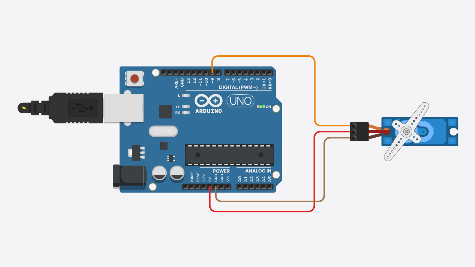
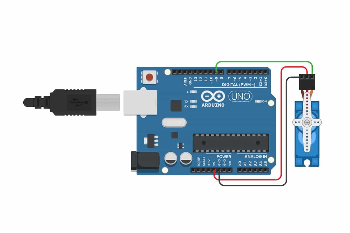
I am trying to implement a knob-controlled step/dir mechanism to drive the motor using Arduino and any necessary circuits.
This is what I have and what I want to achieve. Would anyone give me some suggestions on what can be done using the MCU and/or any necessary external circuits? Any suggestions or useful online examples are highly appreciated.
Thank you!
knob control.png
 

KlausST

Super Moderator
Staff member
Advanced Member level 7
Joined
Apr 17, 2014
Messages
23,242
Helped
4,738
Reputation
9,497
Reaction score
5,125
Trophy points
1,393
Activity points
153,951
Hi,

Code is almost complete available at Arduino IDE.(or available as downloads)
* Step/DIR interface, in "position control".

You just say "run to position x"
Where x = ADC_result × your_factor.
Then the software automatically controls, STEP, DIR does acceleration and deceleration.

It is done many thousands times before. Just do an internet search "arduino step dir position control"

The only thing you have to do is to define your "idle" state. The ADC may be noisy, thus the ADC results may differ a bit from one to the other. No one can define this for you.

Klaus
 

bhl777

Full Member level 6
Full Member level 6
Joined
Sep 30, 2008
Messages
359
Helped
0
Reputation
0
Reaction score
0
Trophy points
1,296
Activity points
5,046
Hi Klause,
Thank you so much! Since "idle" could be a problem due to the noise introduced by ADC, would you recommend just using keeping DIR as the GND for the cases including (1) turning the knob in CCW, and (2) idle?
If there are more considerations that should be considered, would you advise as well?
Thank you!
 

KlausST

Super Moderator
Staff member
Advanced Member level 7
Joined
Apr 17, 2014
Messages
23,242
Helped
4,738
Reputation
9,497
Reaction score
5,125
Trophy points
1,393
Activity points
153,951
Hi,

DIR: for stepper controllers ... I don´t think "high impedance" is a true thrid state.
--> Why do you need "High impedance"?

Usually there is an ENA signal to put the stepper driver into IDLE mode.

For "your idle" state I guess you need some kind of hysteresis. So: as long as the ADC_value is within a small deviation around the last_valid_value you may call this IDLE. Simple software.
Why do you need to detect your IDLE state at all?

Klaus

Btw: I recommend to call it "poti" instead of "knob".
An idea: Why don´t you use an encoder. They look similar to a poti, but have digital output, thus they don´t suffer from the noise problem. Do an internet search for "encoder alps". ALPS is the manufacturer, you may use a different brand encoder.
 

danadakk

Advanced Member level 5
Joined
Mar 26, 2018
Messages
2,282
Helped
350
Reputation
718
Reaction score
527
Trophy points
113
Activity points
10,049
Use an ATTINY85 to gen the PWM and direction signal :

1674904101391.png


Blocks in 3'rd window (copied out of second window) block library, config part. Tool,
mBlock, gens the Arduino code in right hand window to program via Arduino IDE the
ATTINY85. The board you use to program ATTINY85 is an Arduino board like a Nano
or Uno.

But if all you need is a servo controlled by a knob, thats easy too :

1674904688478.png


Here knob V converted to digital with ATTINY85 internal A/D, it ranges from
0 - 1023, then that is mapped to servo angle 0 to 180. and that causes PWM
used internally to alter its pulse width to control angle of servo

mBlock is free.

iu


Here is simple proto of using PWM in ATTINY85 to control a fans speed. Transistor
is used to boost current for the fan. In case of servo it has internal power control for its motor,
so you just tie its control signal to the ATTINY865 PWM output directly.

1674905220642.png


Regards, Dana.
 
Last edited:

danadakk

Advanced Member level 5
Joined
Mar 26, 2018
Messages
2,282
Helped
350
Reputation
718
Reaction score
527
Trophy points
113
Activity points
10,049

Almost forgot, here is all it takes to do a V to Pulse Width converter if thats all you need :

1674915158221.png


Regards, Dana.
 
Last edited:

bhl777

Full Member level 6
Full Member level 6
Joined
Sep 30, 2008
Messages
359
Helped
0
Reputation
0
Reaction score
0
Trophy points
1,296
Activity points
5,046
Hi Klause,
Thank you for your reply. I am using a servo motor that has an encoder in it in the loop. It seems like the encoder integrated with my brushed DC motor is not identical to the encoder you defined.
The following is my block diagram. Would you advise if I change my poti to the "encoder alps", would it bring some extra benefit?
Thank you!
knob control2.png
 

KlausST

Super Moderator
Staff member
Advanced Member level 7
Joined
Apr 17, 2014
Messages
23,242
Helped
4,738
Reputation
9,497
Reaction score
5,125
Trophy points
1,393
Activity points
153,951
Hi,

is not identical to the encoder you defined.
I defined no encoder for the motor.

Now it's a DC motor ... never seen one interfaced with a STEP/DIR interface.

Klaus
 
Last edited:

danadakk

Advanced Member level 5
Joined
Mar 26, 2018
Messages
2,282
Helped
350
Reputation
718
Reaction score
527
Trophy points
113
Activity points
10,049
Dont fortget you can modifiy a servo motor to be a motor :


Regards, Dana
 

bhl777

Full Member level 6
Full Member level 6
Joined
Sep 30, 2008
Messages
359
Helped
0
Reputation
0
Reaction score
0
Trophy points
1,296
Activity points
5,046
Hi Dana,
Thank you for your help! I will go over all the tutorials you shared and post any follow up questions.
--- Updated ---

Hi Klaus,
Since you have known my case, I am trying to evaluate the difference between using the "encoder alps" that you recommended and the poti I already have.
Since my purpose is to convert the knob (a mechanical knob mounted on top of a poti or an encoder) turning behavior to a series of pulses (with a defined frequency, 50% duty cycle), while the number of the pulses is proportional to the angle turned. I somewhat feel using the encoder alps could be a more straightforward way to do so, would you advise from this context?
 
Last edited:

LaTeX Commands Quick-Menu:

Similar threads

Part and Inventory Search

Welcome to EDABoard.com

Sponsor

Top