Continue to Site

Welcome to EDAboard.com

Welcome to our site! EDAboard.com is an international Electronics Discussion Forum focused on EDA software, circuits, schematics, books, theory, papers, asic, pld, 8051, DSP, Network, RF, Analog Design, PCB, Service Manuals... and a whole lot more! To participate you need to register. Registration is free. Click here to register now.

using QTR-1A reflectance sensor with PIC16F877

Status
Not open for further replies.

bogusmeister

Junior Member level 2
Joined
Nov 3, 2010
Messages
21
Helped
2
Reputation
4
Reaction score
1
Trophy points
1,283
Activity points
1,452
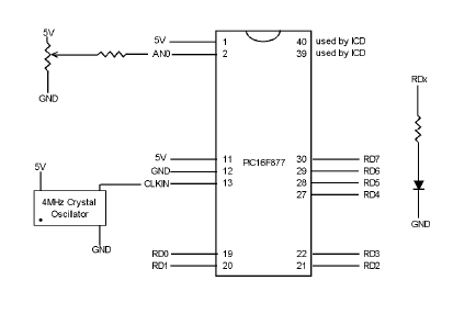
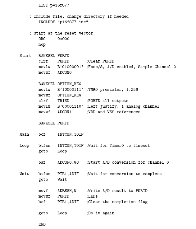
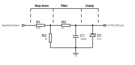
Im using a QTR-1A reflectance sensor (analog) as an input for PIC16F877.. im kinda new in using this PIC, i just used it because of its built-in ADC. i have tried the sample assembly program of ADC using a potentiometer and it worked. but when i replace it with the reflectance sensor. im not getting any output.. pls help me. thanks in advance
 

Could you provide a little more information - such as what signals the sensor provides and how you are physically using them and how you have programmed and interfaced the chip? And what exactly appears to go wrong?

The more info you can give the easier it will be to help.

With the info given I'd say to think about:

Presumably your pot provided a stable slow changing signal whereas a
reflective sensor could provide a rapidly changing and perhaps noisy response.
Also ambient light may make a difference.

jack
 

25_1288942300.jpg


this is the circuit and sample program i have used. then i just replaced the potentiometer with the reflectance sensor which provides voltage signals that usually ranges from 0-5v, but sometimes it goes low (to mV) depends on what material it reflect. what happens is all the led's are turn on and doesn't change.

thank you very much
 

Sorry - you'd need to show the sensor circuit - do you have a link
to the sensor data sheet ?

The thumb sized code image you show doesnt expand - that could be my security software being a bit agressive perhaps if you posted the code here.

I'd also suggest you take a look at a C compiler such as MikroC as these often
come with working examples and in this case they have some very good
tutorial info online from their book.

Your description of what happens could be either hardware or software but actually sounds more software related - perhaps there is someone here
more familiar with the ADC on that chip than myself who could advise
other suggestions.

Also microchip do a really good series of application documents - I'd be suprised if something similar to this wasn't included - try a search on their web site.
(Sorry I dont have mine to hand at the moment I'm changing hardware
and have a lot of stuff archived or I'd have looked it up for you)

jack

jack
 
Hi,
Have you measured the output of the reflectance sensor with a voltmeter. I think you should do that and then report what voltage you normally get? Maybe for some reason the output voltage is too low. There could also be hardware faults such as a sensor fault (don't take this into account yet, as this is very rare), or more commonly a loose connection or an improper connection. Check the connection between your sensor output and PIC input.

Hope this helps.
Tahmid.
 
hi, this is the scenario.. i've tested already the reflectance sensor both with the pic and a voltmeter., i'm getting the reflected input of the sensor from 3 different materials: glass bottle ( 1-2 volts), plastic bottle ( 2.5-3 volts), tin can (22.5volts).... and im already getting a digital output. now my problem is that the digital output that is displayed on the 8leds are not stable. it keeps on changing with the glass bottle and plastic bottle.. but with the tin can the output is steady. how could i get a steady output from that two materials?.. i really need help.. THANKS
 

Hi,
Okay, now this depends on the variation. Post the values you are getting on the 8 LEDs. If they are within a difference of 2-3 (in binary form), it's fine, a good solution would be to take a reading n number of times and averaging them.
As for the tin can, you have a problem there. The 22.5v might fry the PIC. You need to implement your circuit such that the MAX voltage on the PIC input is 5v, lower is preferable.

Hope this helps.
Tahmid.
 
how do i limit my PIC input into 5v or lower?. any suggestion?. what i put after the sensor before it enters the pic that would limit that very high voltage?
 

Okay,
Under all possible or atleast possible to experiment circumstances, measure the sensor output. Say, for substance x, you have 24v and this is your max voltage. In that case, you a voltage divider with resistors 1k and 4.7k to divide your input voltage by 5.7. So now you will get 4.2v for 24v. In your code use the fact that your input voltage is actually 5.7 times that has been read. Then connect a 4.7 or 5.1v zener from the PIC input to gnd, just in case the voltage does climb, in order to protect the PIC.
17_1289309846.jpg

I hope I could make you understand.
Hope this helps.
Tahmid.
 
Status
Not open for further replies.

Part and Inventory Search

Welcome to EDABoard.com

Sponsor

Back
Top