cherne-he
Junior Member level 1

- Joined
- Oct 13, 2014
- Messages
- 17
- Helped
- 0
- Reputation
- 0
- Reaction score
- 0
- Trophy points
- 1
- Activity points
- 131
Hi everyone,
I want to use HFSS to simulate the electromagnetic reflection coefficient of a multi-layer structure (namely electromagnetic absorber), the thickness of each layer of which is about 5 mm, made by dielectric material. The electromagnetic wave, the frequency of which is about 5 GHz, is normal to the planar interface. Our design objective is to attenuate electromagnetic wave reflection.
I created two models described as following:
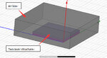
The first model, as shown in the attachment——the first model, consists of a two-layer structure and an air box. The air box include the structure, and the bottom surfaces of the air box and structure are coplanar, the corresponding surfaces of two components in other directions are at a distance of 50 mm. Assign radiation boundary to the air box, choose the bottom face of the structure, which is coplanar to the air box, as the waveport.
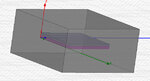
The second model, as shown in the attachment——the second model, is similar to the first model. All the corresponding surfaces of two components are at a distance of 50 mm. Assign radiation boundary to the air box, too. Choose the top and bottom face of the air box as the waveport.
I extract S11 of the two model, but the magnitude is very different.
Could you tell me which method is correct? If both are improper, could you give any suggestion to create a correct model?
Thank you in advance for your help!
With best wishes!
Cherne-he
I want to use HFSS to simulate the electromagnetic reflection coefficient of a multi-layer structure (namely electromagnetic absorber), the thickness of each layer of which is about 5 mm, made by dielectric material. The electromagnetic wave, the frequency of which is about 5 GHz, is normal to the planar interface. Our design objective is to attenuate electromagnetic wave reflection.
I created two models described as following:
The first model, as shown in the attachment——the first model, consists of a two-layer structure and an air box. The air box include the structure, and the bottom surfaces of the air box and structure are coplanar, the corresponding surfaces of two components in other directions are at a distance of 50 mm. Assign radiation boundary to the air box, choose the bottom face of the structure, which is coplanar to the air box, as the waveport.
The second model, as shown in the attachment——the second model, is similar to the first model. All the corresponding surfaces of two components are at a distance of 50 mm. Assign radiation boundary to the air box, too. Choose the top and bottom face of the air box as the waveport.
I extract S11 of the two model, but the magnitude is very different.
Could you tell me which method is correct? If both are improper, could you give any suggestion to create a correct model?
Thank you in advance for your help!
With best wishes!
Cherne-he