kkeeley
Member level 3

- Joined
- Jul 29, 2009
- Messages
- 59
- Helped
- 1
- Reputation
- 2
- Reaction score
- 1
- Trophy points
- 1,288
- Location
- Australia
- Activity points
- 3,043
Hi,
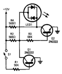
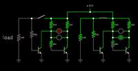
I am wishing to place a small circuit on each of my power rails between my power supply and test circuits so that I can tell when a voltage rail goes over current. I have found a circuit that I think will work nicely for the positive voltage rails, but I'm not 100% sure how to make it work for the negative voltages. Below is an example of the positive voltage circuit, the switch would be replaced by a re-settable fuse and the load would be placed between S1/R1 and ground.

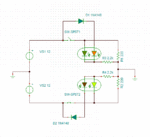
Can I reverse/change the transistors for the negative voltages or will I also need to reconfigure the bias resistors as well. If so what would be the best way to reconfigure the circuit?
Thanks in advance,
Kenneth
I am wishing to place a small circuit on each of my power rails between my power supply and test circuits so that I can tell when a voltage rail goes over current. I have found a circuit that I think will work nicely for the positive voltage rails, but I'm not 100% sure how to make it work for the negative voltages. Below is an example of the positive voltage circuit, the switch would be replaced by a re-settable fuse and the load would be placed between S1/R1 and ground.

Can I reverse/change the transistors for the negative voltages or will I also need to reconfigure the bias resistors as well. If so what would be the best way to reconfigure the circuit?
Thanks in advance,
Kenneth


