Continue to Site

Welcome to EDAboard.com

Welcome to our site! EDAboard.com is an international Electronics Discussion Forum focused on EDA software, circuits, schematics, books, theory, papers, asic, pld, 8051, DSP, Network, RF, Analog Design, PCB, Service Manuals... and a whole lot more! To participate you need to register. Registration is free. Click here to register now.

Use of PISCES POSTMINI TOOL

Status
Not open for further replies.
Contact 4 must be Aliminium of the capacitor will not work properly. Contact 3 does no need to be aluminium.
Try this but put the gate back to n.poly.
If you extract the Id Vd values into excel, then dIds/dVds is just the value of Ids for this cell - Value of Ids for cell above divided by value of Vd for this cell - value of Vd for cell above. Then just plot this colun vs Vds.
 

Hi colbhaidh,

I tried all the possible ways like
contact=1 n.poly
contact=2 neutral
contact=3 Alum cap=5e-12 res=1e1
contact=4 Neutral/Alum

It is converging now only when i am using capacitor & resis together,also when i am changing cap value (to say cap=10e-12) there is no difference in the potential output plots??Kindly help me..Thank you in advance
 

Just to make sure I understand what you want to get from this.
You have a resistor and capacitor on the source side. You drive the source to a voltage, say 1V, run a transient pulse on the gate (on then off) and watch what happens on the drain (and holding capacitor).
The voltage on the source will never change from what you set it to be in Pisces, so you cannot observe any change in the source due to the channel current redistribution when the gate turns off. Pisces is forcing the source voltage, it is never floating.
To see clock read through you can just look at what is happening at the drain and extrapolate this to what would happen at the source under similar circumstances. You could try put a resistor in series with the source and drive the source from the other end of the resistor. This is different from specifying a source resistance which is a contact resistance on the source.

Must you see what happens at the drain and source voltages at the same time?
 
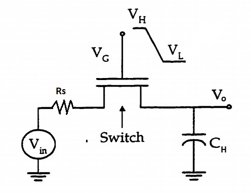
hi colbhaidh thanks a lot for your suggestions...Actually i want a set up similar to the one shown below..

98_1334262138.jpg


So what does "contact=3 Alum cap=5e-12 res=1e1" actually means??? ...Does it indicate the same set up as shown in above figure ??? If not then what does this res=1e1 means??..what should i do to put a series resistance???
 

Then you do not need the source capacitance - take it out. The res=1e1 means the contact resistance of the source and not really a discrete series resistor. It is in ohms per um. I would question whether you need a source resistance if you want to look at the drain holding capacitor only. In a real situation for a symmetrical mos, the source and drain resistances would be about the same around 1-3 ohms per square um.
 

Status
Not open for further replies.

Part and Inventory Search

Welcome to EDABoard.com

Sponsor

Back
Top