Continue to Site

Welcome to EDAboard.com

Welcome to our site! EDAboard.com is an international Electronics Discussion Forum focused on EDA software, circuits, schematics, books, theory, papers, asic, pld, 8051, DSP, Network, RF, Analog Design, PCB, Service Manuals... and a whole lot more! To participate you need to register. Registration is free. Click here to register now.

use 6 thyriseor as SSR in 3PHASE(But dont WORK it)

Status
Not open for further replies.

mohamad0

Newbie level 5
Newbie level 5
Joined
Aug 14, 2015
Messages
10
Helped
0
Reputation
0
Reaction score
0
Trophy points
1
Activity points
75
Hi dear friends
i use 6 thyristor as switch in 3 phase like below:
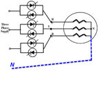
SCR6_1.jpg

i trigger each thyristor on zero time in its phase . (i use zero crosing).
it work when neutral is connect on star center .but it don't work when the neutral wire is disconnected .

what is the problem ?

i think for example in first time when thyristor's R phase is triggered because other thyristors are off it can't turn on (there is no way for flow the current in load )like below:
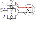
SCR6_.jpg

but when the neutral is connected there is a way to flow current in load like below:
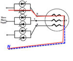
SCR6_N.jpg

-----------
now please help me to solve the problem .
how must i trigger thyristors that work circuit with out neutral wire?
thanks a lot .
best regards.

@i am sorry because my english isn't good.
 

Hi,

because other thyristors are off it can't turn on
That's the key point.
Obviously you have to trigger at least two SCRs at the same time to enable current flow.

For full motor voltage you have to trigger thee SCRs at a time.
Like:
R+, S-, T-
R+, S+, T-
R-, S+, T-
R-, S+, T+
R-, S-, T+
R+, S-, T+

Klaus
 
Any reason why you don't trigger the thyristors continuously, e.g. by a pulse train?

If you analyze the problem thoroughly, you see that the required trigger time differs from circuit with neutral if some switches are not yet conducting.

Solid state relays with zero crossing logic derive the trigger timing from the actual voltage across the switch rather than an expected phase voltage, one solution for the problem. The other is to enable the trigger continuously.

Without the neutral connection, one SCR pair can be omitted, by the way.
 
thank you for your answer ,dear klaus .

R+, S-, T-
R+, S+, T-
R-, S+, T-
R-, S+, T+
R-, S-, T+
R+, S-, T+
is your mean that i must trigger tristor's ( R+, S+, T-) on zero crosing of R phase ?
if not , please explain me more .
thank you dear klaus .
 

Any reason why you don't trigger the thyristors continuously, e.g. by a pulse train?

If you analyze the problem thoroughly, you see that the required trigger time differs from circuit with neutral if some switches are not yet conducting.

Solid state relays with zero crossing logic derive the trigger timing from the actual voltage across the switch rather than an expected phase voltage, one solution for the problem. The other is to enable the trigger continuously.

Without the neutral connection, one SCR pair can be omitted, by the way.
thank u dear FvM
i sense zero crossing each phase than neutral . not than other phase .
 

Hi
my intention is on/off a 3 phase heater (250KW) .
in real i want control the temperature with PWM . but i need to reduce bad harmunic that it inject to network .
 

Hi,

(sorry for the wrong order of posts)

What´s the intention of your circuit?
Just switching ON/OFF a load?

Klaus

- - - Updated - - -

Hi,

confusing.

ON/OFF is clear.

But how do you think you can do PWM while maintianing zerc cross switching to avoid harmonics. Please draw a timing diagram.

SCR:
* to switch them ON: the voltage across THE SCR needs to be in correct direction. The gate trigger current needs to be high enough.
* to keep them ON: the load current needs to be high enough
* to switch them OFF... the load current needs be be less than it´s holding threshold. This usually this is very close to current zero cross.
* you can´t switch them OFF with gate control.

*****************
just ON/OFF controll for a heater.
* I recommend to use some long time ON/OFF. Like wave train control.
* then switch ON at a random timing.
* continous triggering with pulse train.

Else it will be difficult, because you need to start two (one positive, one negative) SCR when the voltage across BOTH lines is zero. This is not when line voltage (wrt N) is zero.
Then you need to trigger the third line usually 90° later.

Klaus
 
SCR relays can implement full wave switching rather than "PWM". Switching resistive loads at voltage zero crossing is possible, but control is a bit tricky due to relation of phase-to-phase voltages, as previously addressed.

You can buy three-phase solid state relays that switches at zero crossings, simply on-off controlled by a DC level. A reasonable on-off period for heater control is 1 to several 10 seconds, depending on the heater time constant.
 

Hi,

250kW is a lot. I assume this is in an industrial environment.

I assume the heat is not produced by three pieces of 83kW each?
If possible I recommend to use multiple combinations of heating elements to adjust the heating energy.
For fine regulation you could control only one smaller 3phase heating element. Maybe connected in star to ease control circuit.

Klaus
 
hi
your recommend is good .
but my means is it :
scr.jpg
 

Hi,

you show a single phase system only. This is not realistic.

It´s easy to simulate a three phase system with excel.

Generate three phases.
Generate 6 switches
calculate the resulting star_voltage
calculate the resulting line_currents

****
Or you could do with a simulation tool.
Or you could read some documentation.

Klaus
 

hi
dear friend .
i don't know how to simulate a 3 phase system in excel .
please introduce document about my problem and design three phase ssr .
(i have education MATLAB)
regurds
 

oh
What exactly is the problem with excel?
One column with phase angle. the first row is 0, all the next are the value before plus X (where X is your desired stepsize in degree)
One column with R line voltage: "= 1.41 * 240 * sin (angle *pi() / 180)"
One column with S line voltage: "= 1.41 * 240 * sin ((angle-120) *pi() / 180)"
One column with T line voltage: "= 1.41 * 240 * sin ((angle-240) *pi() / 180)"
and so on.
i know it . (i know that wave in three phase is how .

please in future do those basic search on your own.
dear friend . i searched a lot and i design and make a circuit .
i am no a Lazy boy , dear friend .
but i ask question to find the problem .
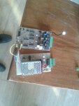
i use of pulse transformer for gate trigger .
it's my circuit (pcb):
photo_2017-07-29_19-13-42.jpg


and its zero crossing circuit :
zero.jpg
 

Hi,

did you try an internet search about "three phase zero cross swtiching"?
Then you immediately find documents like this: https://www.fairchildsemi.com/application-notes/AN/AN-3004.pdf
--> please in future do those basic search on your own.

What exactly is the problem with excel?
One column with phase angle. the first row is 0, all the next are the value before plus X (where X is your desired stepsize in degree)
One column with R line voltage: "= 1.41 * 240 * sin (angle *pi() / 180)"
One column with S line voltage: "= 1.41 * 240 * sin ((angle-120) *pi() / 180)"
One column with T line voltage: "= 1.41 * 240 * sin ((angle-240) *pi() / 180)"
and so on.

Klaus

- - - Updated - - -
(here should be post#13)

Hi,

but i ask question to find the problem .
The problem is clear. The answer is given already. In forum posts and in application note.

The other problem is that you think as if it a single phase system with reference to N. But it is a three phase system. It is different. You have to accept this.

So what answer do you expect?

Klaus
 
The other problem is that you think as if it a single phase system with reference to N. But it is a three phase system. It is different. You have to accept this.

OK dear friend . it's true .
i will modify the circuit according to your guide .
because i use of pulse trans former ,must i use of which zero crossing? i must sense zero crossing between two phase like below :
zero.jpg
 

Hi,

because i use of pulse trans former ,must i use of which zero crossing?
No, not because of pulse transformer.
You only need zero cross detection because you said you want to avoid harmonics.

--> you have to decide if you want zero cross switch ON or not.

Klaus
 

hi
i want zero cross detection .

i must put zero cross detection on thyristor like above picture?(in above post)
 

Hi,

please tell exactly how you want to process the zero cross signal.

What I mean: I see only one zero cross detection circuit. With it you can detect 2 events per full wave. But you don´t recognize if it is falling or rising zero cross.
Then how to generate 6 gate signals? How did you decide to do that?

At least take a piece of paper and a pencil and draw the voltages, currents, timings...

Klaus
 
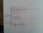
hi dear friend .
i draw the commutation and zero crossing point .
20170826_131049.jpg

but i dont know when i must fire the thyristors.
on commutation point ?which thyristor ?
best regards
 

Re: use 6 thyristor as SSR in 3PHASE(But dont WORK it)

Why commutation points?

Here's the Ltspice simulation of a 3phase-SSR model using MOC3081 opto triacs with zero crossing detector, producing current waveforms with minimal DC components and harmonics.

At shows that the trigger time shifts between first turn-on and continuous operation. You should specifically take care to avoid an odd number of half waves in phase currents because it involves a DC component and might cause transformer saturation.

3phase_ssr.png
 

Attachments

  • 3phase_SSR.zip
    2.3 KB · Views: 112
Status
Not open for further replies.

Part and Inventory Search

Welcome to EDABoard.com

Sponsor

Back
Top