Welcome to our site! EDAboard.com is an international Electronics Discussion Forum focused on EDA software, circuits, schematics, books, theory, papers, asic, pld, 8051, DSP, Network, RF, Analog Design, PCB, Service Manuals... and a whole lot more! To participate you need to register. Registration is free. Click here to register now.
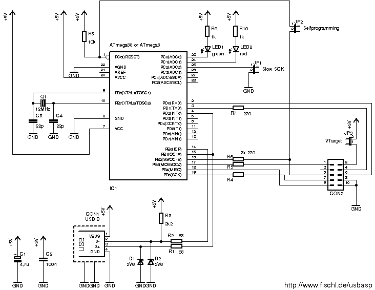
I'm no expert on USB, but in this case I think the zeners are needed - the microcontroller operates on 5V, but the USB data lines don't, as far as I know. The zeners (and resistors) will protect to a degree. It looks like some crude interface, but possibly it will work.
1. Did you program the microcontroller with the Hex file for USBASP programmer?
2. Did you also installed the USB driver for usbasp (if you are testing this programmer on windows)?
3. Are you sure that the USB D+ and USB D- pins are not exchanged?
without programming the hex file and installing the windows driver the PC side application will not recognize this circuit.
Purpose of zener diodes: Since the microcontroller used in this programmer circuit is using CMOS / TTL level pins for USB interface and this microcontroller does not has actual USB interface built in to it. And since in actual usb inteface the signals do not go above 3.6V therefore in my opinion the circuit uses Zener diodes to clip the voltage above 3.6 to comply USB signal voltage levels.
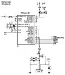
the schematic which i have posted is from fishel di website..i have made this..usb driver is installed in my pc..i have programmed hex file also..but still its saying usb device not recognised..i have connected the diodes before 68 ohm resistor..is it the mistake??
- - - Updated - - -
i have connected the diodes in this way..please help..
- - - Updated - - -
i have used atmega8..
- - - Updated - - -
what is the difference if i connect diodes before or after 68 ohm resistor??
My friend that circuit is not from https://www.fischl.de I show in post #3 circuit from that site, circuit work without any problem, make exact like that circuit and there is no problems.
You see in upper left corner of circuit picture there is text "modified"!
Differences is obvious, there is no need for commenting on that.
This site uses cookies to help personalise content, tailor your experience and to keep you logged in if you register.
By continuing to use this site, you are consenting to our use of cookies.