Continue to Site

Welcome to EDAboard.com

Welcome to our site! EDAboard.com is an international Electronics Discussion Forum focused on EDA software, circuits, schematics, books, theory, papers, asic, pld, 8051, DSP, Network, RF, Analog Design, PCB, Service Manuals... and a whole lot more! To participate you need to register. Registration is free. Click here to register now.

USB power

Status
Not open for further replies.

Rajinder1268

Full Member level 3
Joined
Mar 20, 2021
Messages
162
Helped
1
Reputation
2
Reaction score
4
Trophy points
18
Activity points
1,228
Hi,
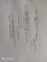
I have a microcontroller which is flashed via the PC through USB and FTDI. The FTDI is is powered internally (3V3).
I also need an external 3V3 LDO @600mA to power the rest of my circuitry i.e. BLE device etc.
Is there going to be any issue with me connecting the GND from USB to the main PCB GND?
Also is it ok to have the microcontroller programmed via FTDI 3V3 (it will only be flashed occasionally) and the rest of my circuitry from a 12V to 3V3 generated from a LDO or buck regulator. Are there any potential issues?
 
Hi,

many potential issues.. .. depending on your circuit.
I guess a textual description can not show the whole story.

Thus we need a draft including all the parts involved, wiring and power supplies.

Klaus
 

Hi
Here is a block diagram. The issue is do I power the FTDI from its internal 3V3 which can deliver around 50mA or from the output of my buck regulator?
It would mean even without the PC connected through the microUSB the FTDI will be powered up with 3.3V.
Are there any issues? Can I disable the internal 3.3V of the FTDI (FT231x)?
 

Attachments

  • IMG_20220504_080048.jpg
    IMG_20220504_080048.jpg
    1.4 MB · Views: 77

Hi,

block diagram:
A lot of informations missing:
* where does the 12V power come from?
* where does the PC get it´s power from?
* where do the FTDI outputs go to?

do I power the FTDI from its internal 3V3 which can deliver around 50mA or from the output of my buck regulator?
The FTDI is happy with 50mA. So why do you want to power it from external supply? Wht´s the idea behind it?

Whether the FTDI can stand external power supply and what to care for is written in it´s datasheet / application notes. Although I used FTDI ... I don´t have these informations in my head. So I had to read the datasheet. Better you do this first.

Are there any issues? Can I disable the internal 3.3V of the FTDI (FT231x)?
--> Datasheet

Klaus
 

Hi,

block diagram:
A lot of informations missing:
* where does the 12V power come from?
* where does the PC get it´s power from?
* where do the FTDI outputs go to?


The FTDI is happy with 50mA. So why do you want to power it from external supply? Wht´s the idea behind it?

Whether the FTDI can stand external power supply and what to care for is written in it´s datasheet / application notes. Although I used FTDI ... I don´t have these informations in my head. So I had to read the datasheet. Better you do this first.


--> Datasheet

Klaus
Hi
12V is from car battery, FTDI outputs to microcontroller TX RX pins to allow flash programming. PC power to microUSB via USB.
Perhaps my initial question was not clear.
Can I power the FTDI with its internal 3.3V regulator, as I have another buck 12V to 3.3V on the circuit to power external circuits. Would powering the FTDI via 3V3 internally and the rest of my circuitry from my buck regulator cause any issues as the 3V3 is generated from different sources? TIA.
 

Can I power the FTDI with its internal 3.3V regulator
If I´m not mistaken thats the standard method.... and shown in the datasheet.

Would powering the FTDI via 3V3 internally and the rest of my circuitry from my buck regulator cause any issues as the 3V3 is generated from different sources?
This is alo a standard situation. The programmer has it´s supply and the application has it´s supply.

Nothing different to a PC and a printer (both mains powered) have individual supplies...and datalines between them.

What to take care of:
* Avoid to connect both supplies
* (early) connect both GNDs
* expect ESD when connecting. --> Protect your signal lines.
* Don´t force a HIGH signal to an unpowered device (wihtout beeing sure the device can withstand this). Often the valid input voltage range is: "GND - 0.6V" --- to "VCC + 0.6V". This means: if power is down, then VCC = 0V and thus the upper limit is +0.6V for applying external signals.

I recommend to add the diagram with all informations, because it´s hard to combne all informatons form differnt posts and text and diagrams. This leads to misunderstanding of the whole problem.

Klaus
 

If I´m not mistaken thats the standard method.... and shown in the datasheet.


This is alo a standard situation. The programmer has it´s supply and the application has it´s supply.

Nothing different to a PC and a printer (both mains powered) have individual supplies...and datalines between them.

What to take care of:
* Avoid to connect both supplies
* (early) connect both GNDs
* expect ESD when connecting. --> Protect your signal lines.
* Don´t force a HIGH signal to an unpowered device (wihtout beeing sure the device can withstand this). Often the valid input voltage range is: "GND - 0.6V" --- to "VCC + 0.6V". This means: if power is down, then VCC = 0V and thus the upper limit is +0.6V for applying external signals.

I recommend to add the diagram with all informations, because it´s hard to combne all informatons form differnt posts and text and diagrams. This leads to misunderstanding of the whole problem.

Klaus
Hi
Thanks for your help. I have added ESD protection for the USB side. I will have a separate 3V3 for the FTDI and separate for the rest of my circuitry. The GND's will need to be connected but the 3V3 will not. I will label them differently in the schematic, which I am still creating (hence could only show a block diagram).
 

The keywords for the questions asked in post #3 are bus-powered versus self-powered operation of the FTDI device. If there's no need of having part of your circuit powered by the USB, you'll decide for self-powered. USB power line is only used to sense plug/unplug then but not powering the device.
 
ESD:

in your diagram there are signals "Tx" and "Rx".
If you connect/disconnect them to a microcontroller you will need ESD protection at the FTDI_Tx, FTDI_Rx, MCU_Tx and MCU_Rx.
If they have a fix connection (traces on a PCB for example) you don´t need ESD protection.

Klaus
 

Status
Not open for further replies.

Similar threads

Part and Inventory Search

Welcome to EDABoard.com

Sponsor

Back
Top