Continue to Site

Welcome to EDAboard.com

Welcome to our site! EDAboard.com is an international Electronics Discussion Forum focused on EDA software, circuits, schematics, books, theory, papers, asic, pld, 8051, DSP, Network, RF, Analog Design, PCB, Service Manuals... and a whole lot more! To participate you need to register. Registration is free. Click here to register now.

up/down event counter 6 digits

Status
Not open for further replies.

gie_b_hsb

Junior Member level 2
Joined
Oct 30, 2006
Messages
23
Helped
1
Reputation
2
Reaction score
0
Trophy points
1,281
Activity points
1,446
event counter circuit

please guys, i need up/down event counter 6 digits circuit which the circuit having start, stop n reset button.:cry:
 

8 digits counter schematic

gie_b_hsb said:
please guys, i need up/down event counter 6 digits circuit which the circuit having start, stop n reset button.:cry:
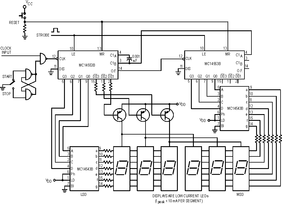
How about implementing it with a microcontroller (e.g., pic16f877)? You can use general purpose i/o pins as follows:
  • 6 for active digit selects
  • 7 for digit segment selects
  • 1 for start switch
  • 1 for stop switch
  • 1 for reset switch
Be sure to include code to debounce the switches in software for reliable operation.
 

event counter schematic

Complete schematic without microcontroller

26_1162345190.gif
 

cd40110be

budhy, that looks like an up-only counter. He's looking for up-down.

A microcontroller would be a nice solution.
 

hobby event counter

**broken link removed**

I;ve personally build this, working.....
If u wan to have six 7-seg, just modify the schematic (add 2 more 40110 ICs), and the wiring do as the previous one, then should be ok......
 

8 digit up down counter projects

how to get CD40110BE datasheet or technical specification
 

event counter electronic circuit

echo47 wrote
budhy, that looks like an up-only counter. He's looking for up-down.

you right, I'm forget he need up down counter! Thx.

gie_b_hsb wrote:
how to get CD40110BE datasheet or technical specification

CD40110BE is the right chip for you project, there is the data sheet:
 

6digit event counter circuit

Dear all
Thank’s a lot for attention and cooperation.
After read and compare between the proto board and the schematic, i think they are have differences, in the proto board the capacitor is used but in the schematic no capacitor used And then I see the two 10 K resistor fixed in the proto board but in the schematic only one fixed, please advice me…?

My planning is build this counter until 8 seven segment display. Do you help me, please? I’m not understand about other option ( in web page) to addition a Clock Circuit with a Frequency of 1 Hz. What differences if using and not Clock Circuit with a Frequency of 1 Hz ?
:|
 

up down counter

4 pcs Capasitor is Bypass Capasitor to minimize power supply current spikes, without them the circuit running well too

One resistor in inpute circuit, and 1 resistor (optional) is to placing decimal point (see right most section of the scematic).

1) Adding a Clock Circuit with a Frequency of 1 Hz in place of the Reset Switch will create a Frequency counter in Hz/Sec.

Above sentence is self explain
 

8 digit up down counter circuit

Dear Budhy
if i use the capacitor how to connect the pin capacitor to other component(i.e IC).
 

    V

    Points: 2
    Helpful Answer Positive Rating
Status
Not open for further replies.

Part and Inventory Search

Welcome to EDABoard.com

Sponsor

Back
Top