Continue to Site

Welcome to EDAboard.com

Welcome to our site! EDAboard.com is an international Electronics Discussion Forum focused on EDA software, circuits, schematics, books, theory, papers, asic, pld, 8051, DSP, Network, RF, Analog Design, PCB, Service Manuals... and a whole lot more! To participate you need to register. Registration is free. Click here to register now.

UNL2003AN Ground output

Status
Not open for further replies.

edtruji

Newbie level 5
Joined
May 21, 2012
Messages
10
Helped
0
Reputation
0
Reaction score
0
Trophy points
1,281
Activity points
1,354
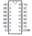
I'm working with ULN2003AN (DATASHEET),
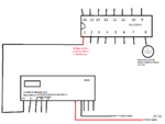
I'm attaching the ULN2003An to a board call the RXD4 (Board Specifications)., RXD4 come with 2 wireless beepers.

PIN#1 from UNL2003AN solder to PIN#D3 from RXD4.
D3 output 5V 9A when I press the beeper button.

What I need is that when I press the beeper button, the ground should come momentarily on any of the UNL2003AN pins.

In the #8 pin from UNL2003AN, I always have ground and when I press the beeper button the ground leaves momentary.
What I need is exactly the opposite of the behavior I'm getting on PIN8.


I'm a newbie in electronics. Please keep that in mind.


V__9891.png


UNL2003AN + RXD4 Fixed Image.png
 
Last edited:

The outputs of the RXD4 should be inverted before connecting to the uln.
If you are using only one output of the uln you can replace the whole IC with 2 transistors one acting as an inverter and the other as a switch to ground.
If you want to use the 4 outputs of the RXD4 you can use 4 outputs of the uln and use the remaining 3 circuits of the uln as inverters as chuckey said. Then you need an extra transistor acting as an inverter for the last output.
To use the uln as an inverter dont forget to connect a pullup resistor.
 

@albert22
Yes I'm using the 4 outputs of RXD4.
RXD4 D3 OUTPUT -> UNL PIN 1
RXD4 D2 OUTPUT -> UNL PIN 2
RXD4 D1 OUTPUT -> UNL PIN 3
RXD4 D0 OUTPUT -> UNL PIN 4

can use the remaining 3 circuits of the uln as inverters as chuckey said?
How?

@chukie
uln 2003 pin 8 gets its input from pin 1, where does this come from? .
From RXD4 D3.


If you have unused sections on the uln, you can wire these up as inverters.
How?


In my previous post I was reading pins of the UNL2003 the wrong way. Sorry for that. Already fixed the image. Remember I'm new to the electronics world.

**broken link removed**

RXD_Circuit 4140.png
 

Attachments

  • UNL2003AN + RXD4 Fixed2 Image.png
    UNL2003AN + RXD4 Fixed2 Image.png
    21.9 KB · Views: 61
Last edited:

Maybe what I need is a NPN transistor? But which one, that can handle 5V 9A? How can I add a NOT gate to the D3 output:?:
 

Attachments

  • COM.PNG
    COM.PNG
    5.9 KB · Views: 60
Last edited:

RXD4 D3 OUTPUT -> UNL PIN 1
RXD4 D2 OUTPUT -> UNL PIN 2
RXD4 D1 OUTPUT -> UNL PIN 3
RXD4 D0 OUTPUT -> UNL PIN 4

You can try this:
RXD4 D3 OUTPUT -> UNL PIN 1
RXD4 D2 OUTPUT -> UNL PIN 2
RXD4 D1 OUTPUT -> UNL PIN 3
UNL PIN 16 -> UNL PIN 4
UNL PIN 15 -> UNL PIN 5
UNL PIN 14 -> UNL PIN 6
Pins 14,15 and 16 each with a 1k resistor to +5v
This should get you 3 outputs working as you need
How can I add a NOT gate to the D3 output
For the following I used RXD4 but you can rewire as you like.
For RXD4 you need a 2n2222 NPN transistor or similar. The NOR gate or inverter can be made as>
RXD4 to a 4k7 resistor to the base. Emitter to gnd. Collector to a 1K resistor to +5v. Collector also to ULN Pin 7.

Maybe what I need is a NPN transistor? But which one, that can handle 5V 9A?
I dont understand why do you need a 9A NPN. The uln2003 only goes to 500mA.


Attachment 91537
??
 

Status
Not open for further replies.

Part and Inventory Search

Welcome to EDABoard.com

Sponsor

Back
Top