dom444
Junior Member level 2

- Joined
- Jul 9, 2009
- Messages
- 23
- Helped
- 0
- Reputation
- 0
- Reaction score
- 1
- Trophy points
- 1,283
- Location
- Australia
- Activity points
- 1,462
After looking for a true sine wave pwm inverter circuit suitable to build I came across very little helpful information and some teasers of micro chip 50/60hz pwm programs that don't work or are not accurate enough,
as well as some half presented projects. so I decided to make my own from information i managed to find around.
I am presenting this to any one that wants to use it it is scalable so can be used as the bases of an inverter of any power, I have found the forums very helpful and my way of giving something back.
if any one can think of some improvements or mistakes let me know.
the design is not entirely mine but i added to the excellent work of romanblack.com and uses an 8 pin 12f675 pic chip to generate the pwm sine wave it has adjustable over current shut down built in and only needs 12volts input,
I also have the shutdown pin on the headers in case you want to add temp or low batt shutdown as well just needs 5v high to kill the output.
I will follow up with the schematic when i get a chance to draw it up.
you only need to change from 12mhz crystal for 60hz to 10mhz for 50hz. And you only need 4 four transistor or IGBT's and 340volts DC to get 240v ac and a suitable filter to get true sine and filter out the high frequency's
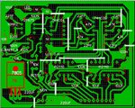
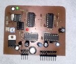
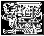
my test board shown produces an accurate 50hz and very nice sine wave when i tested with a 47k resistor and 100n cap filter on my scope.
Attachments
Last edited:


