frilance
Member level 1

- Joined
- Aug 16, 2012
- Messages
- 37
- Helped
- 0
- Reputation
- 0
- Reaction score
- 0
- Trophy points
- 1,286
- Activity points
- 1,703
Hi everyone!
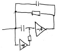
I'm working on a rather simple transimpedance amplifier (TIA) for a photodiode. I split the photodiode current into an AC and a DC path, since I need both outputs. For each of them I use a different amplifier and a different compensation capacitor. With the values you can see in the attached schematic , I get a frequency response that satisfies me. The problem comes when I measure the actual frequency response of the implemented device. As you can see in the other attachment
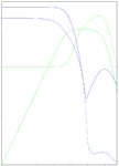
  there is a strange behavior somewhere between 30 and 40 MHz in the AC channel and I have no idea what could produce it... I'm not really worried with the peaks in both channels at really high frequencies (100 MHz - 200 MHz) cause it's out of the range I need...
Some ideas about what could be happening here? Some unwanted interaction between both channels?
Thank you so much in advance.
Best Regards.
I'm working on a rather simple transimpedance amplifier (TIA) for a photodiode. I split the photodiode current into an AC and a DC path, since I need both outputs. For each of them I use a different amplifier and a different compensation capacitor. With the values you can see in the attached schematic
 , I get a frequency response that satisfies me. The problem comes when I measure the actual frequency response of the implemented device. As you can see in the other attachment
  there is a strange behavior somewhere between 30 and 40 MHz in the AC channel and I have no idea what could produce it... I'm not really worried with the peaks in both channels at really high frequencies (100 MHz - 200 MHz) cause it's out of the range I need...
 Some ideas about what could be happening here? Some unwanted interaction between both channels?
Thank you so much in advance.
Best Regards.


