Continue to Site

Welcome to EDAboard.com

Welcome to our site! EDAboard.com is an international Electronics Discussion Forum focused on EDA software, circuits, schematics, books, theory, papers, asic, pld, 8051, DSP, Network, RF, Analog Design, PCB, Service Manuals... and a whole lot more! To participate you need to register. Registration is free. Click here to register now.

Understanding the Phase response of FIR filter

Status
Not open for further replies.

susane

Newbie level 6
Joined
Apr 12, 2016
Messages
14
Helped
0
Reputation
0
Reaction score
0
Trophy points
1
Activity points
128
Hi everyone

I am working on ECG signal capturing using ADS1292R connected with Arduino uno,
Luckily i found an FIR filter library for arduino, i included that in my code, but i dont know which type of filter is it.
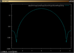
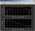
So i used the filter coefficients to plot the phase response in matlab. but i am not really good with signal processing,
Can any one help me understand this phase response?
What type of filter is it?
sampling frequency is 125Hz

FIR.jpg
 

Hi,

I assume the constant slope is caused by a constant delay. Typical for a digital filter.
The jump is in the magnitude of 1 x PI = 180°. therefore I assume it is caused by a (filter) resonance at this frequency.
(At first i thought it is the jump at 360° but then it should be 2 x PI)

Klaus
 

Hi Klaus
So is it a low pass filter or a band pass?
 

Hi,

I assume a band stop at 50Hz. Just to suppress mains frequency.

Is this reasonable?

It´s really hard to say just with a phase plot. Don´t you have a gain or amplitude plot?
There are free tools in the internet, where you can give your FIR parameters and it prints the plots.

Klaus
 

and what are the names of these tools?

My FIR coefficients are { 0.021, 0.096, 0.146, 0.096, 0.021};
 

Hi,

I don´t remember, it was some years ago.

I´m sure you can find it on your own ;-)


Klaus
 

You can plot magnitude characteristics easiliy by gnuplot.
Here x=omega/fsample=2*pi*freq/fsample, fsample=Sampling Frequency

Code:
j = {0.0, 1.0}
h0 = 0.021
h1 = 0.096
h2 = 0.146
h3 = 0.096
h4 = 0.021
set xrange [-pi:pi]
plot abs(h0+h1*exp(-j*x)+h2*exp(-2*j*x)+h3*exp(-3*j*x)+h4*exp(-4*j*x))

This FIR filter is simple Lowpass type.

If you have MATLAB or Octave, you can confirm more easiliy.

Code:
w=linspace(-pi, pi, 1000);
b=[0.021, 0.096, 0.146, 0.096, 0.021];
a=1;
freqz(b, a, w)
Both gnuplot and octave are freeware.
 

Attachments

  • 160511-213555.png
    160511-213555.png
    8.5 KB · Views: 106
  • 160511-215600.png
    160511-215600.png
    12.1 KB · Views: 100
Last edited:
  • Like
Reactions: susane

    susane

    Points: 2
    Helpful Answer Positive Rating
Hi,

This FIR filter is simple Lowpass type.
My imagination of a "simple" low pass filter is a RC low pass filter. (Others may see this differentely)
This filter IS a low pass filter, but it behaves somehow differentely to an RC LPF.

You can see the huge attenuation at about 0.84.
What does 0.84 here mean?
Sampling frequency is 125Hz. So nyquist frequency is 62.5Hz. This 62.5Hz ar normalized to be "1".
Now 0.84 x 62.5Hz = 52.5Hz. (point of most attenuation)

--> The attenuation at 50Hz is about 40dB (referenced to the attenaution at 0Hz).
(To improve attenuation at 50Hz you could adjust sample frequency to 120Hz instead 125Hz)

Klaus
 

Hi pancho_hideboo

That was really helpfull, i am quite new to these stuff you may think that i am asking stupid questions but i want to learn.
Now my second question is

its a quiet basic question

If i use a band pass filter of 1hz
it means that it will give me only the signals that are repeating after every second right?
 

My imagination of a "simple" low pass filter is a RC low pass filter. (Others may see this differentely)
This filter IS a low pass filter, but it behaves somehow differentely to an RC LPF.
If you would like to emulate RC Low pass Filter, you have to use IIR filter like digiltal integrator of 1/(1-a*z^-1).

I think this FIR emulate simple Window function such as Hanning, Hamming, etc.

If i use a band pass filter of 1hz
it means that it will give me only the signals that are repeating after every second right?
Do you mean BPF of center frequency is equal to 1Hz ?

Frequency Characteristics of Digital Filter is repeated with period=sampling frequency.

Your sampling frequency is 125Hz.
Period of frequency characteristics is 125Hz.

So if center frequency is 1Hz, 1Hz, 124Hz, 125Hz, 249Hz, 251Hz, ..... are pass frequencies.
 
Last edited:
  • Like
Reactions: susane

    susane

    Points: 2
    Helpful Answer Positive Rating
Yes i mean BPF of center frequency equal to 1 Hz

But i am sorry, i didnt understand your last point about the pass frequencies,
What i want is to filter Heart Beat from a BIA signal

My sampling rate is 125Hz
assuming that the heart beat will occur once every second, that is 1 Hz.

I am using Matlab FDA tool.
Can you tell me what should be my frequencies for a BPF?
 

Last edited:
  • Like
Reactions: susane

    susane

    Points: 2
    Helpful Answer Positive Rating
Hi,

I think this FIR emulate simple Window function such as Hanning, Hamming, etc.
Isn't hanning 1-cos(x)? Or something like that?
In my eyes a window function is not compareable with a FIR filter.
The FIR filter has a fixed input stream an output stream..no dedicated count of samples.

A window function like hanning often is used before a FFT for a fixed array of samples. Usually 2^n samples.

*******
So if center frequency is 1Hz, 1Hz, 124Hz, 125Hz, 249Hz, 251Hz, ..... are pass frequencies.
One can explain this with nyquist..or undersampling...where analog frequencies that are larger than half of the sample frequency are mirrored to so called "alias frequencies".
Not exactely the same, but similar.

If there are alias frequencies (because of an inappropriate anti aliasing filter) then it is impossible to differentiate between true frequencies and alias frequencies.

Klaus
 

There's a direct relation between window function and FIR impulse response if you look at the FIR direct synthesis method. In brief, you get the FIR coefficient sequence by calculating the fourier transform of the intended filter frequency characteristic and apply a window function.

In any case, you shouldn't expect sophisticated filter properties from a FIR filter with just 5 taps.
 

Status
Not open for further replies.

Part and Inventory Search

Welcome to EDABoard.com

Sponsor

Back
Top