Continue to Site

Welcome to EDAboard.com

Welcome to our site! EDAboard.com is an international Electronics Discussion Forum focused on EDA software, circuits, schematics, books, theory, papers, asic, pld, 8051, DSP, Network, RF, Analog Design, PCB, Service Manuals... and a whole lot more! To participate you need to register. Registration is free. Click here to register now.

Understanding Delta Sigma Modulation in simulink

Status
Not open for further replies.

jack3128

Newbie level 2
Newbie level 2
Joined
Mar 23, 2013
Messages
2
Helped
0
Reputation
0
Reaction score
0
Trophy points
1,281
Visit site
Activity points
1,292
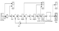
Hi Guys, i'm new in this forum and hope to learn from u you all ^^. I'm learning 2nd order sigma delta Modulation that simulate in Matlab/simulink but i dont understand the block funtion such as why use Gain, why feed back loop , why use integral and so on. Can some one help explain the block diagram plz. :grin:
 

Hi Jack,

A sigma delta modulator consists of one feedback loop around an integrator and a quantizer. This integrator (since you have 1/S therefore continuous) producing a low pass filtering of the input signal and a high pass filtering of the quantization noise which is injected at the quantizer, hense noise shaping the noise out of band. Since you have a second order system, you have 2 integrators and two feedback paths. (You can have feedforward or feed ins but this is more advanced, please reference DSM books). Additionally, since you now have a chain of integrators, you therefore needs coefficient scaling of your integrator gains to ensure stability. That is why the gain blocks are used. If you don't have the Gain block infront, your integrators have a gain of 1.. hence 1/S. This scaling is then used, to keep your integrator swings within limits of your designs. This can be seen when looking at the scopes you have probing each node.

Hope this helps,
JGK
Hey Thx alot for the information u really help me alot by explain these block TQ VERY MUCH ^^:lol:
 

Status
Not open for further replies.

Similar threads

Part and Inventory Search

Welcome to EDABoard.com

Sponsor

Back
Top