amitaiwe
Member level 3

Hi,
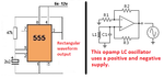
I have build up a metal detector circuit based on this implementation:
https://www.instructables.com/id/How-to-make-a-cheap-and-simple-metal-detector/
I am trying to figure out it's working operation.
This implementation appears in a lot of sites in the web but there's no real explanation of what's going on there and why are the specific components chosen.
In theory the LC's frequency is f=1/(2*pi*sqrt(LC). I used a 22uF cap and 33mH inductor which produced a 440hz frequency.
by theory it's supposed to be 186hz - that's more then times two. Now of course that the 555 is influencing this result via the (I think) astable frequency and I am trying to understand how.
Shortening up the two legs of the inductor results in a square wave with 2.6hz frequency and shortening up also the two legs of the capacitor results in a 4.54khz frequency. all frequencies I measured in the 555's output (pin 3).
Can anyone help me or direct me how to figure out the working operation?
Thanks,
Amitai