Continue to Site

Welcome to EDAboard.com

Welcome to our site! EDAboard.com is an international Electronics Discussion Forum focused on EDA software, circuits, schematics, books, theory, papers, asic, pld, 8051, DSP, Network, RF, Analog Design, PCB, Service Manuals... and a whole lot more! To participate you need to register. Registration is free. Click here to register now.

unable to drive IR LED with common transformerless power supply

Status
Not open for further replies.

rajaram04

Advanced Member level 3
Joined
Jun 17, 2012
Messages
871
Helped
6
Reputation
12
Reaction score
5
Trophy points
1,298
Location
earth
Visit site
Activity points
7,687
Hello sir

with normal designings for transformerless power supply i desined so many circuits & got brilliant results for red white blue green LEDs but with same power supply i am unable to drive an IR LED to the full . . i am getting too much weak IR rays unable for a detector to detect it , i need this kind of IR LED operation for my personal experiments so please help . .. thanks

this basic type arrangment i am using

tsp.jpg

just in place of 820k resistor i am using 1 meg & rest diagram is same
but unable to drive IR LED with 47k resistor in series with it . .please help thanks

IR LED i am using
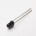
irled.jpg
 

what are the specs for the IR LED? Vd? Max Current?

- - - Updated - - -

Use CAUTION when using mains voltage. I URGE you to use a 12VDC power supply FIRST, then move to your circuit.

- - - Updated - - -

it APPEARS that the more common IR LEDs need at least 20mA

http://www.everlight.com/datasheets/IR333_H0_L10_datasheet.pdf
 

what are the specs for the IR LED? Vd? Max Current?

- - - Updated - - -

Use CAUTION when using mains voltage. I URGE you to use a 12VDC power supply FIRST, then move to your circuit.

- - - Updated - - -

it APPEARS that the more common IR LEDs need at least 20mA

**broken link removed**


kk sir but these are only parameters for a device
but i need to know how to generate such ratings from transformerless power supply ??
 

If I can paraphrase FvM ... you need to provide much more information for someone to help you because what you
have said does not make enough sense to do so.
A full circuit diagram at the very least.
I also urge you to listen to KAM1787.
And just my own opinion but - NEVER use a transformerless power supply - even more so when you don't really know what you are doing.
 

First, let us calculate the impedance of Cx:

X_cx = 1 / (2 * PI * F * Cx )
X_cX = 1 / (2 * 3.14 * 50 * 470e-9)
X_cx = 6773 Ohm

Next, let us assume the series equivalent resistance with Cx is close to zero. The RMS current would be:

I_rms = V_rms / X_cx
I _rms = 220 / 6.773 = 32.5 mA

I_peak = I_rms * SQRT(2)
I_peak = 32.5 * 1.4141 = 46 mA

I_dc = I_peak * 2 / PI (full wave rectifier)
I_dc = 46 mA * 2 / 3.14 = 29.2 mA

As you see:
I_dc = 0.9 I_rms in this case.

The above calculations are good if there is no filter capacitor (C1) and no series resistor with the IR LED.

Do you want me to continue?
 

If I can paraphrase FvM ... you need to provide much more information for someone to help you because what you
have said does not make enough sense to do so.
A full circuit diagram at the very least.
I also urge you to listen to KAM1787.
And just my own opinion but - NEVER use a transformerless power supply - even more so when you don't really know what you are doing.


respected sir in the very first post i explained everything , so i just answered what fvm asked about a single simple resistor which is in series with IR LED . . i did it for protection purpose , its a value not much greater not much less so i choosed that value , other LEDs are working fully but my issue deals with IR LED so i started the thread . .
 

I hope that, from my post #7, you deduced that if the series resistor 47K is removed (R_series = 0):
I_irLED = I_dc = 29.2 mA

Note:
This will be the same if the LED is red, orange, yellow, green or white. All LED forward voltages are negligible relative to the 220 Vrms.

If you like decreasing I_led, it can be done by decreasing the value of Cx.

For instance I use this simple low-cost circuit to dectect the water lever in a tank (conductive hence acts like a neutral line). But I use a very small capacitor so that its current won't harm a human body but enough to light a sensitive LED ;)
 
Last edited:

I hope that, from my post #7, you deduced that if the series resistor 47K is removed (R_series = 0):
I_irLED = I_dc = 29.2 mA

Note:
This will be the same if the LED is red, orange, yellow, green or white. All LED forward voltages are negligible relative to the 220 Vrms.

If you like decreasing I_led, it can be done by decreasing the value of Cx.

For instance I use this simple low-cost circuit to dectect the water lever in a tank (conductive hence acts like a neutral line). But I use a very small capacitor so that its current won't harm a human body but enough to light a sensitive LED ;)


ya ya sir absolutly , iam studying that full explanations only for now , its amazing , just a one shot method to solve any of the problem
thanks sir , if there is any doubt i ll ask you that , first let me learn it fully
 

First, let us calculate the impedance of Cx:

X_cx = 1 / (2 * PI * F * Cx )
X_cX = 1 / (2 * 3.14 * 50 * 470e-9)
X_cx = 6773 Ohm

Next, let us assume the series equivalent resistance with Cx is close to zero. The RMS current would be:

I_rms = V_rms / X_cx
I _rms = 220 / 6.773 = 32.5 mA

I_peak = I_rms * SQRT(2)
I_peak = 32.5 * 1.4141 = 46 mA

I_dc = I_peak * 2 / PI (full wave rectifier)
I_dc = 46 mA * 2 / 3.14 = 29.2 mA

As you see:
I_dc = 0.9 I_rms in this case.

The above calculations are good if there is no filter capacitor (C1) and no series resistor with the IR LED.

Do you want me to continue?


yes sir please continue now :razz:
 

I understand that if the LED is not IR, one likely builds this circuit to get some light only. In this case, to get light, it doesn't matter the shape of the LED current as long the current is below the LED ratings (average and peak) so that its useful life is relatively long.

But by using an IR LED, it means there is a sort of IR receiver too in order to detect the LED IR beam. In this case, the LED current shape is important and it may vary from one application to another.

What do you think?
 

Why don't you run you IR LED at 50% or 75% of max current rating? If max current rating is 100 mA then use a series resistor which limits the IR LED current to 50 mA.


hmm kk agree , so what would be the value of that series resistor ?

- - - Updated - - -

I understand that if the LED is not IR, one likely builds this circuit to get some light only. In this case, to get light, it doesn't matter the shape of the LED current as long the current is below the LED ratings (average and peak) so that its useful life is relatively long.

But by using an IR LED, it means there is a sort of IR receiver too in order to detect the LED IR beam. In this case, the LED current shape is important and it may vary from one application to another.

What do you think?


hmm ya that i agree ok . . so whats the current rating for IR LEDs ?
 

Check the datasheet of your IR LED. You have to give 36 or 38, or 40 KHz square wave for the IR LED. If voltage across IR LED is 5V and current should be 50 mA then 5V/50 mA gives the value of series resistance.
 

Check the datasheet of your IR LED. You have to give 36 or 38, or 40 KHz square wave for the IR LED. If voltage across IR LED is 5V and current should be 50 mA then 5V/50 mA gives the value of series resistance.


ohh i see , okk then how to generate that 40 khz ? any circuit diagram relating it ?
 

You are using a transformerless PSU in a water tank application direct from mains - sorry I dont know about your original post but fuses? even?
Incidently dont forget your IR led will use much less power if you are pulsing it (and can handle higher current that way)
 

What is your IR detector?
Is it an IR receiver IC that detects IR only at a certain frequency? It will ignore your IR fed from DC.


hmm ya it was a single transistor switching unit , but after this post of you i applied an amflying stage befor the IR detector diode & swtching unit . Now its working very fine too fast .
So please tell if i replace the circuitry with an IC circuit then would it draw more current or voltage than previous or would become a unit on operating less power parameters ? (ignore speed)

- - - Updated - - -

What is your IR detector?
Is it an IR receiver IC that detects IR only at a certain frequency? It will ignore your IR fed from DC.


hmm ya it was a single transistor switching unit , but after this post of you i applied an amflying stage befor the IR detector diode & swtching unit . Now its working very fine too fast .
So please tell if i replace the circuitry with an IC circuit then would it draw more current or voltage than previous or would become a unit on operating less power parameters ? (ignore speed)
 

An IR receiver IC works at a few frequencies around 38kHz to avoid continuous IR from the sun and from incandescent light bulbs.
But modern compact fluorescent light bulbs also work at around 38kHz.
Therefore the IR receiver IC has a circuit inside that reduces the gain (AGC) when there is continuous IR or continuous pulsed IR at around 40kHz.

A TSOP1738 IR receiver IC datasheet shows that it draws 0.4mA to 1.5mA from 5V.
 

Status
Not open for further replies.

Part and Inventory Search

Welcome to EDABoard.com

Sponsor

Back
Top