Continue to Site

Welcome to EDAboard.com

Welcome to our site! EDAboard.com is an international Electronics Discussion Forum focused on EDA software, circuits, schematics, books, theory, papers, asic, pld, 8051, DSP, Network, RF, Analog Design, PCB, Service Manuals... and a whole lot more! To participate you need to register. Registration is free. Click here to register now.

Ultrasonic transmitter high voltage and load driver.

Status
Not open for further replies.

Dino1400

Full Member level 1
Joined
Sep 22, 2010
Messages
95
Helped
2
Reputation
4
Reaction score
2
Trophy points
1,288
Activity points
1,941
Hello All,

I made typical ultrasonic transmitter based on 555 timer, and because needed to boost the signal for long distance I have to drive the transmitter with high voltage (up to 40V from the datasheet). for that used a NPN transistor that can handle the 40V. Now, I'm having the issue that the transistor can not drive the transmitter load the signal become week and distorted. I have attached the circuit, please provide me with some guidance.\

Thank you all in advance.
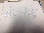
IMG_5414.JPG
 

Hi,

Have you had a look at the NPN datasheet to see if anything related to hFE is affecting it? The collector current is meant to be 1mA or 13mA? - Is that a 2k2 or 22k resistor? What's going into the base, 2mA? Is the base high voltage around 3.5V, and is that enough to fully turn it on?/Have you measured the "high" voltage coming out of the 555 output pin? What's the load resistance/current requirements? Maybe the 555 output voltage is lower than needed/expected at 40kHz.

The load is powered when the NPN is off, and the load is bypassed/off by the NPN when it is turned on, isn't it?

It may also be that the timer output voltage just isn't enough to turn the transistor on and you would need to cascade two transistors.

You may need to provide more information about the BJT and the transmitter, or some measurements/oscilloscope observations for anyone to take the time to answer, I'm afraid.

I'm not an engineer, but I've at least tried to help with constructive comments and what I know a little about. Hope you've solved the problem, anyway.
 

Your response is good:

The timer output is fine outputting a square wave at 5V. The timer by itself can drive the transmitter with no problem. However, when I try to load the transmitter to a NPN start having this issue, because I need pulses at 30V for long distance. The PNP has a max 6 Volt VBE and a 40V VDS(max). The collector resistors I have tried 10K and 2.2K. Any idea on a buffer circuit that can drive the transmitter that has a capacitance of 2.7nF center frequency of 40KHz.
 

Hi,

The BJT just pulls down the transducer voltage
A weak pullup (2.2k) limits the output power.

--> I recommend a push pull driver (with an additional BJT that actively pulls up the transducer voltage)

Klaus
 

Error of reasoning is to think of the transducer as a capacitive load. It isn't. 2.7 nF is only valid at low frequencies, at the resonance frequency the transducer has a real impedance of several 100 ohms. Respectively you need a lower impedance driver.
 
Status
Not open for further replies.

Part and Inventory Search

Welcome to EDABoard.com

Sponsor

Back
Top