tokoivun
Newbie level 1

- Joined
- Apr 8, 2015
- Messages
- 1
- Helped
- 0
- Reputation
- 0
- Reaction score
- 0
- Trophy points
- 1
- Activity points
- 15
Feeling a bit silly but here goes the question.
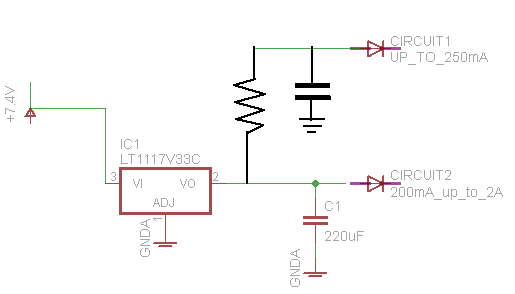
My intention is to drive two separate circuits from a single power source (battery, 2x 3.7V Li-Ions in series, getting 7.4V out).
The schematic goes like this:

So, I'd basically have 2x LD1117V33C voltage regulators after the battery, one before each circuit. The first circuit operates an AVR plus other minor stuff, taking 3.3V and about 200mA max. The second circuit operates on 3.3V as well, normally taking 20mA-200mA, but there are very short spikes of 2A draw (bluntly put, it'll be a SIM908 or similar), hence the 220uF capacitor in the schema. according to the docs a 100uF capacitor should be enough so 220uF might be a bit of an overkill.
And now to the question itself...
Do I need to put in any additional protection to the first circuit or will it be unaffected by the short current spikes that circuit 2 is pulling periodically?
Another question as well. Do I actually need two regulators or would one suffice if I threw in a capacitor for circuit 1 as well?
Also, ignore the led icons in the schematic") Couldn't find a proper abstraction to describe a circuit
Couldn't find a proper abstraction to describe a circuit
My intention is to drive two separate circuits from a single power source (battery, 2x 3.7V Li-Ions in series, getting 7.4V out).
The schematic goes like this:
So, I'd basically have 2x LD1117V33C voltage regulators after the battery, one before each circuit. The first circuit operates an AVR plus other minor stuff, taking 3.3V and about 200mA max. The second circuit operates on 3.3V as well, normally taking 20mA-200mA, but there are very short spikes of 2A draw (bluntly put, it'll be a SIM908 or similar), hence the 220uF capacitor in the schema. according to the docs a 100uF capacitor should be enough so 220uF might be a bit of an overkill.
And now to the question itself...
Do I need to put in any additional protection to the first circuit or will it be unaffected by the short current spikes that circuit 2 is pulling periodically?
Another question as well. Do I actually need two regulators or would one suffice if I threw in a capacitor for circuit 1 as well?
Also, ignore the led icons in the schematic
Couldn't find a proper abstraction to describe a circuit
Last edited: