Continue to Site

Welcome to EDAboard.com

Welcome to our site! EDAboard.com is an international Electronics Discussion Forum focused on EDA software, circuits, schematics, books, theory, papers, asic, pld, 8051, DSP, Network, RF, Analog Design, PCB, Service Manuals... and a whole lot more! To participate you need to register. Registration is free. Click here to register now.

Two ADC channels at a time ( pic16f73 )

Status
Not open for further replies.

hamid159

Full Member level 3
Full Member level 3
Joined
Aug 25, 2013
Messages
176
Helped
14
Reputation
28
Reaction score
14
Trophy points
1,298
Location
Lahore
Visit site
Activity points
2,488
Hy guyz,i'm working on volt and ammeter.( 130V max. and about 40A )
Problem is that which parameter either voltage or current i connect to 'AN0' works fine.but the other parameter don't give constant value.i.e, fluctuating.first of all i connect the voltage to 'AN0' and worked fine.but current was varying on lcd.and then i connected the current (voltage across shunt ) to 'AN0'...satisfied.. but voltage was again altering...Here is code in C.


Code C - [expand]
1
2
3
4
5
6
7
8
9
10
11
12
13
14
15
16
17
18
19
20
21
22
23
24
25
26
27
28
29
30
31
32
33
34
35
36
37
38
39
40
41
42
43
44
45
46
47
48
49
50
51
52
53
54
55
56
57
58
59
60
61
62
63
64
65
66
67
68
69
70
71
72
73
74
//sbit Led at RB0_bit;
sbit LCD_RS at RC2_bit;
sbit LCD_EN at RC3_bit;
sbit LCD_D4 at RC4_bit;
sbit LCD_D5 at RC5_bit;
sbit LCD_D6 at RC6_bit;
sbit LCD_D7 at RC7_bit;
sbit LCD_RS_Direction at TRISC2_bit;
sbit LCD_EN_Direction at TRISC3_bit;
sbit LCD_D4_Direction at TRISC4_bit;
sbit LCD_D5_Direction at TRISC5_bit;
sbit LCD_D6_Direction at TRISC6_bit;
sbit LCD_D7_Direction at TRISC7_bit;
char *l,*m,*q,*v,y[7],u[7],n[7],o[7];
unsigned int k,j,i,b,a;
unsigned int x;
float t;
void main() {
float z;
ADCON1 =0b00000000;
TRISA=0b00100001;
TRISC=0x00;
lcd_init();
lcd_cmd(_LCD_CURSOR_OFF);
while(1)
{
t = ADC_Read(4);
z=ADC_Read(0);
k=t;
k=k*5.2499;
j=k/10;
i=k%10;
inttostr(j,o);
inttostr(i,n);
l=ltrim(o);
m=ltrim(n);
if ((j<=99)&&(j>9)){
Lcd_out(1,7,l);
lcd_out(1,9,".");
Lcd_out(1,10,m);
}
else if (j<=9)
{
      Lcd_out(1,7,l);
lcd_out(1,8,".");
Lcd_out(1,9,m);
}
else {
Lcd_out(1,7,l);
lcd_out(1,10,".");
Lcd_out(1,11,m);
}
         //Ampere
                x=z;
x=x*2.793;
b=x/10;
a=x%10;
inttostr(b,y);
inttostr(a,u);
q=ltrim(y);
v=ltrim(u);
if (b<=9){
Lcd_out(2,10,q);
lcd_out(2,11,".");
Lcd_out(2,12,v);
}
else {
Lcd_out(2,10,q);
lcd_out(2,12,".");
Lcd_out(2,13,v);
}
 Delay_ms(500);
}
}


Thanks for your reply.
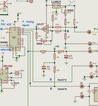
Here is schematic diagram.No,i'm not using any filter or CM choke.Is it necessary?if yes,Then what type of filter or choke i should use?
 

Attachments

  • pic16f73_volt_and_ammeter.pdf
    31.3 KB · Views: 129

Sorry but that schematic is horribly drawn and is electrically nonsense.

I think what you are trying to do is measure voltage on AN4 and current on AN0 but the measurement points are incorrect and the impedances are completely mismatched.

Brian.
 

hello,

Sorry but that schematic is horribly drawn and is electrically nonsense.
i am agree with betwixt,
you better have to do your schematic by hand and take a photo

do You want to measure 130V max or U bat 25V ?
Divide by 10 values for R1 and R2
R1=68K (0,5W) R2= 2.7K
so, you get 0.95V for 25V BAT1
or 4.96V for 130V DC


if R10 is the shunt, the measure must be take on other side of R10 , battery side
Hot point... other side is 0V
LM324 must be powered with symetrical power +12 and -12 or +6 and -6V
better use is rail to rail AOP like LTC271

The best is to Use an ACS712-50A hall effect transducer to measure the Amps.
 

Thanks for the reply.
sorry guyz i've disturbed you with such a horrible schematic..There were also some mistakes.Now here is updated version.
Betwixt, what do you mean by mismatched impedence?
Paulfjujo,i want to measure 130V (i've a variable smps with 120V max )
yes R10 is my shunt..i mistakenly connected the ground to +ve terminal of op amp.now i have made it right in updated version.op amp is amplifying the signal (voltage across shunt ) with about 50 gain.and then there is voltage divider whose output (half of opamp output )is fed to 16f73 ( AN0 ).But the problem is that which signal either current ( in voltage form) or voltage i take to AN0 of pic works fine but not at any other pin..i want to measure both voltage and current simultaneously..
-ve supply (op amp negative supply) is used while amplifying -ve signal.but i'm only amplifying signal in positive direction (dc signal ).That's why i have only used +12v with ground.
 

Attachments

  • updated_version.pdf
    26.2 KB · Views: 116
Last edited:

Your voltage measurement will include the drop across R10, it would be more accurate if you swapped the ground and R6 connections to the opposite sides of R10. Also bear in mind that your circuit will be extremely critical of layout around R10.

There is only one ADC inside a PIC so you can't take two measurments at a time, you have to take one, change ADC channel and take the other.

My impedance comment was because the ADC settling time and accuracy in a PIC depends upon the impedance of the source feeding it. As well as using an op-amp that was capable of rail-to-rail output, I would drop R7 to say 2.2K and replace R8 with a diode (anode to ground) to prevent negative excursions. I'm not sure why you added the 0.1uF capacitor to the voltage measurement but not the current measurement, if noise is a problem add one across the diode I just mentioned as well.

The 680K/27K divider could do with reducing, try making the 27K no more than about 5K and adjusting the 680K accordingly. Alternatively, you could buffer the voltage with an op-amp before sending it to the PIC.

Brian.
 

thanks betwixt..i want to measure both current and voltage ( so need two adc modules ).is this impossible to measure current and voltage simultaneously ( using pic16f73 ) or there is any possible method to do so?
 

i want to measure both current and voltage ( so need two adc modules ).is this impossible to measure current and voltage simultaneously ( using pic16f73 )

You can reduce interval between current and voltage conversions, so that can minimize effect arising from phase shift on acquisition, although according to your circuit, inputs are continuous model.


+++
 

if you want to keep your PIC with only one ADC input
you can add a multiplexeur like CD4052 or Analog switch like CD4046
to measure Volt, then Amps...
but you never will take these 2 measures in the same time.. even impossible with a PIC with 2 analog input..

What means simultaneous... 2 measures in the same µS ...impossible
but to get 2 measures within 50µS .. that is possible . but not every 50µS
if you have other job to do with the PIC...
it depends of the time scale you are using...

time is relatif if we discuss about nS, µS,mS,....

exemple with CD4052 :
selection 1 on 4 measure with 2 pins output of the PIC (connected to A,B)
4 analog input X0..X3
output of multiplexer goes to analog input of PIC


Image1.jpg
 

but datasheet (CD4052) says, ON resistance is 270 ohms for VDD =5V and VEE =0V..i think this is quite large.isn't it?
 

do a test
apply 1V on adc input, get the value
add 270 ohms in serial and do again the measure ...and compare
and you will feel easy
 

Status
Not open for further replies.

Similar threads

Part and Inventory Search

Welcome to EDABoard.com

Sponsor

Back
Top