jasensio
Junior Member level 1
Hi everyone!
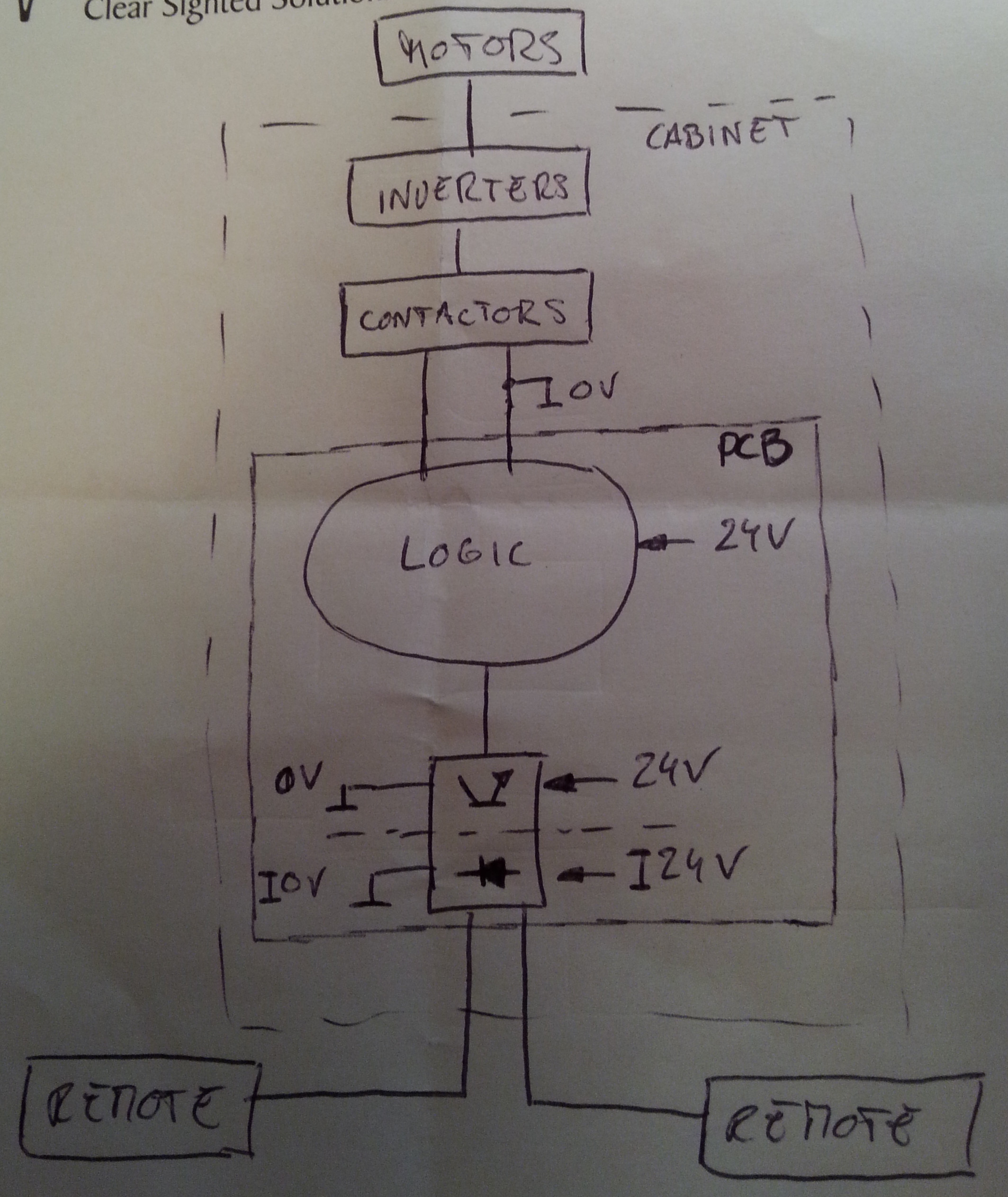
I have got a PCB with two separated blocks, with independent power supplies and I/O connectors in both sides.
Gnd in the picture is chassis ground. It will converge with the other two pcb grounds (0V and I0V) close to the power input connectors, and from that point a single wire will connect with system chassis.
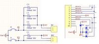
I know that each TVS diode should be placed close to the connector and give it a low inductance path to ground.
But my question is...which ground? Surge currents should be conducted to chassis, shouldn't they?
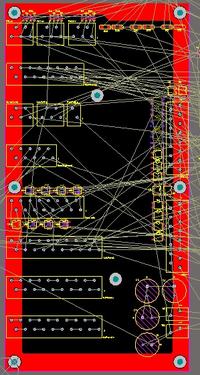
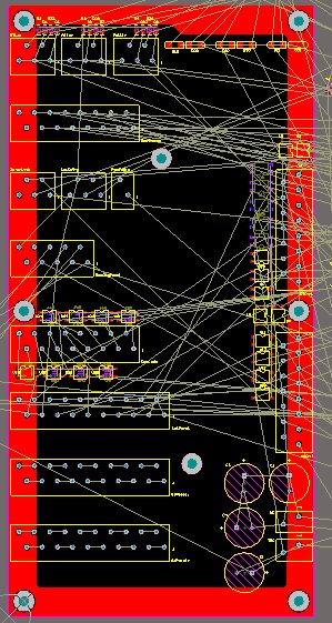
I will have solid internal ground planes for 0V and I0V, and I was thinking of create another plane on external layer for chassis ground and use it to tie all TVS's directly to it...something like this:
Regards
I have got a PCB with two separated blocks, with independent power supplies and I/O connectors in both sides.

Gnd in the picture is chassis ground. It will converge with the other two pcb grounds (0V and I0V) close to the power input connectors, and from that point a single wire will connect with system chassis.
I know that each TVS diode should be placed close to the connector and give it a low inductance path to ground.
But my question is...which ground? Surge currents should be conducted to chassis, shouldn't they?
I will have solid internal ground planes for 0V and I0V, and I was thinking of create another plane on external layer for chassis ground and use it to tie all TVS's directly to it...something like this:
Regards