Continue to Site

Welcome to EDAboard.com

Welcome to our site! EDAboard.com is an international Electronics Discussion Forum focused on EDA software, circuits, schematics, books, theory, papers, asic, pld, 8051, DSP, Network, RF, Analog Design, PCB, Service Manuals... and a whole lot more! To participate you need to register. Registration is free. Click here to register now.

Turning off the signal to MCU at desired voltage level

Status
Not open for further replies.

Vaughn

Junior Member level 2
Joined
Feb 8, 2013
Messages
23
Helped
0
Reputation
0
Reaction score
0
Trophy points
1,281
Location
India
Activity points
1,520
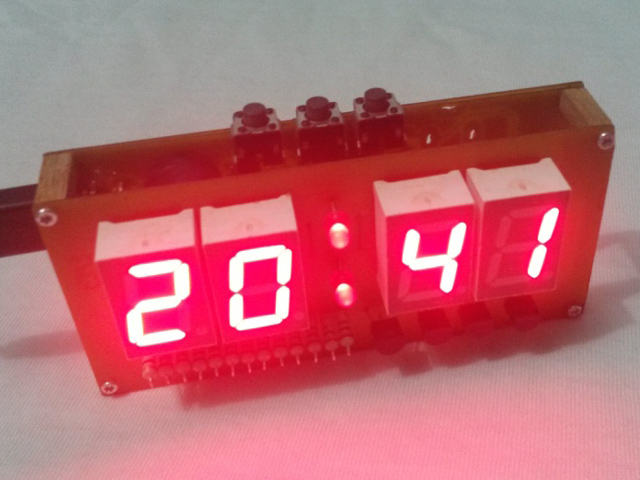
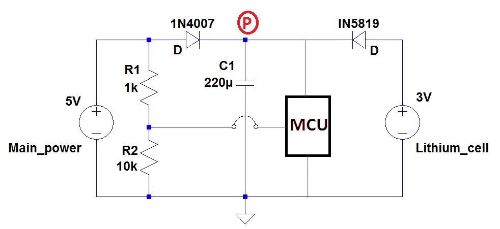
I am designing a digital clock using atmega8 without external RTC chip, In this project two power supply is being used one main power 5V and another 3V power from lithium battery, when there is main power available 7segment displays the time and when the main power gets disconnected 7segment is made turned off and MCU goes into sleep mode, draws power from lithium battery, so the my problem is I want to design a circuit which will be sending voltage 4.7V or above to MCU pin when there is main power available and the ground as soon as voltage drops below the 4.7V. How can I achieve this using a 4.7V zener and few resistors without transistors?
 

A zener diode won't do it. You need a comparator IC and a voltage reference (maybe a zener diode). You could do it with an LM10 (8-pins IC) and a few resistors since the LM10 has an opamp that can be used as a comparator and it also has an adjustable voltage reference.
 
  • Like
Reactions: Vaughn

    Vaughn

    Points: 2
    Helpful Answer Positive Rating
Not a very precision is required I just want to turn off the display before power switches to lithium battery say before MCU power reaches to ~3.9V (3V battery+ little gape), and don't want to use any complicated because I want to make a compact clock.
 

Hi,

you may need to add some hysteresis.
I expect the voltage to rise at the same time when the display is switched OFF. --> it switches ON again, then OFF... and so on.

Klaus
 
  • Like
Reactions: Vaughn

    Vaughn

    Points: 2
    Helpful Answer Positive Rating
So can you please explain me how can I manage these issues without a complex circuit, currently I'm managing things as the image below, but the problem with this circuit is when I abruptly disconnect the pin from clock it works well but when I unplug the adapter from the board and leaving the pin connected display gets dim for ~4 seconds then off, but time does not gets lost.


Hi,

Is it possible to supply the display with the power left side of the 1N4007? This may be an easy solution without any additional device.

***
The 4s delay probably is caused by the adapter´s inside capacitor. So the voltage drops slowly. Then the threshold voltage to detect "LOW" is too low.

Consider to use a supply voltage monitoring circuit. Sounds difficult, but it is not. A single three pin device instead of your two resistors.
Look for LM809 or MAX 809. There are different threshold levels you can choose.

Hope this helps

Klaus
 
  • Like
Reactions: Vaughn

    Vaughn

    Points: 2
    Helpful Answer Positive Rating
Very well said sir, This will be a very good option to put the display left to the 1N4007 However I solved this problem by putting a 2.7V zener in the place of R1 and replacing R2 with 1K, Now it is working fine, Hope if all settled. Thank you all.
 

Hi,

Is it possible to supply the display with the power left side of the 1N4007? This may be an easy solution without any additional device.

***
The 4s delay probably is caused by the adapter´s inside capacitor. So the voltage drops slowly. Then the threshold voltage to detect "LOW" is too low.

Consider to use a supply voltage monitoring circuit. Sounds difficult, but it is not. A single three-pin device instead of your two resistors.
Look for LM809 or MAX 809. There are different threshold levels you can choose.

Hope this helps

Klaus

how can I implement this device when the MCU is already drawing 8uA in sleep mode and datasheet says LM809/10 sinks 15uA I can't provide it VCC from the battery because don't want the power consumption become more than it. and reset voltage is ~3.9V
 
Last edited:

Hi,

The LM809 (or similar) are supervisory circuits.
The output is a logic level signal to assert !RST or to assert an !INT signal.
(maybe you could connect it to an Int input. Trigger on falling edge. Within the ISR disable the display. Software clock still is running.
With every second_update you could poll the Int status to enable the display in case the supply is powered on again)

The output CAN NOT supply current to drive a microcontroller. It is no power output signal.

I guess the 8uA is necessary to keep the software clock running...

Klaus
 

Did you consider to use the inbuilt ADC for battery voltage measurement?
 

Hi,

good idea.

Or even easier: Use the built in comparator.

Klaus
 

Status
Not open for further replies.

Part and Inventory Search

Welcome to EDABoard.com

Sponsor

Back
Top