Continue to Site

Welcome to EDAboard.com

Welcome to our site! EDAboard.com is an international Electronics Discussion Forum focused on EDA software, circuits, schematics, books, theory, papers, asic, pld, 8051, DSP, Network, RF, Analog Design, PCB, Service Manuals... and a whole lot more! To participate you need to register. Registration is free. Click here to register now.

Tuning trace on Switching power AC/DC

Status
Not open for further replies.

xandeyes

Junior Member level 1
Joined
Nov 22, 2013
Messages
17
Helped
1
Reputation
2
Reaction score
1
Trophy points
3
Activity points
138
Hi Guys,

When I disassemble a machine "made in China", it has a AC/DC module low-power ( I guess it's 12V/1A output).

I observe these design and discover something weird. It has (look like) the tuning traces and serial with MOV. MOV'name is "vdr 10d561k"
As in my picture below.
It is connected directly to 220VAC input before come into capacitor and common choke.

So, what is the purpose of this tuning trace ??
It's the first time I see this kind, please explain clearly.
Thank you.
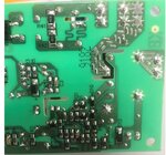
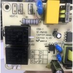
bottom.jpgtop.jpg
 

I'd consider it useless respectively inappropriate. May be someone had the idea of creating a fuse in case of MOV failure. But using PCB traces as fuse doesn't comply with safety rules. Presumedly R1 will act as fusing resistor.
 

Not a tuning trace although it looks like one. I think this is thin traces being used as a fuse in case the MOV breaks down. Not a good idea but cheaper than a glass fuse.

Brian/
 

Hi,

I also think it's a fuse.

But I also think it's counter productive.
If the fuse breaks down, then the MOV can't do it's job anymore and high voltage will enter the application.
--> Better use a fuse at the power input, then in case the fuse blows the MOV still prevents the application from overvoltage.

Klaus
 

It is irrelevant. The pcb designer was bored, and made something for fun more likely. It serves no useful known purpose.
 

I agree with idea it represents fuse.

There are 2 "tuning traces" , but in my board, it has only one is connected to MOV, the other is "waited" for other options.
In case designer want to increase current through circuit, he will solder the terminal of 2 traces, than, 2 traces are parallel.

Those are my predictions, thank for your kind answer.
 

Status
Not open for further replies.

Similar threads

Part and Inventory Search

Welcome to EDABoard.com

Sponsor

Back
Top