Continue to Site

Welcome to EDAboard.com

Welcome to our site! EDAboard.com is an international Electronics Discussion Forum focused on EDA software, circuits, schematics, books, theory, papers, asic, pld, 8051, DSP, Network, RF, Analog Design, PCB, Service Manuals... and a whole lot more! To participate you need to register. Registration is free. Click here to register now.

Troobleshooting 450w amplifier

Status
Not open for further replies.
Are your answers in this post a joke?

Yes.

I did not learn electronics as a proper course (unlike many of you) and I picked it up as a hobby as I grew up. I can figure out, many times correctly, how many young students, who have skipped a couple of classes, feel and often get lost. I hope you will agree that most circuit diagrams do not explain the functioning or operation of the circuit the way you have done. It is easy to get lost.
 

There is more chance of them working.

You might be able to use the 'C' versions of the TIP35 and TIP36 but the 'A' and 'B' versions do not have enough voltage rating. According to the data sheets, all the transistors have the same pin spacing.

Compare the transistors:

Elliot, MJL4281A/MJL4302A , VCEO = 350V, IC = 15A, PD = 230W.
Yours, 2SC3856/2SA1492, VCEO = 180V, IC = 15A, PD = 130W.
TIP35C/36C, VCEO = 100V, IC = 25A, PD = 125W.

As you can see there are significant differences even in those basic characteristics.

The diodes generate almost no heat and need no heat sink of their own, they should be thermally bonded to the heatsink used by the output transistors which will get VERY hot! I would consider it a design mistake if the thermal bonding was ignored as the bias point of the transistors would drift with temperature change. If the PCB doesn't allow contact you can always mount the diodes on the transistor heatsink and run wires to them.

Brian.
 

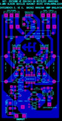
I need something soon so Ill skip on the repairs of that one for now I found a next amp that I want to try hopefully its ok, I cannot find a circuit diagram for it but it has the pcb layout.


It is not really difficult to trace out the circuit schematic from a PCB layout- particularly if it is a single sides one. Once you do that, it will be nice to spend some time on the roles of individual components (on who is doing what) in the overall circuit performance. It will be part boring and part rewarding: but far more satisfying that just getting a board and soldering the components.
 

The diodes MUST be mounted on the heatsink for the output transistors to avoid thermal runaway where heat causes more current in the output transistors that causes more heat that causes more current that causes more heat .... meltdown! Bolt a piece of metal to the heatsink and it can press the diodes against the heasink. Use some thermal grease to aid heat transfer to the diodes. Run wires from the diodes to the pcb.
 

Status
Not open for further replies.

Similar threads

Part and Inventory Search

Welcome to EDABoard.com

Sponsor

Back
Top