Continue to Site

Welcome to EDAboard.com

Welcome to our site! EDAboard.com is an international Electronics Discussion Forum focused on EDA software, circuits, schematics, books, theory, papers, asic, pld, 8051, DSP, Network, RF, Analog Design, PCB, Service Manuals... and a whole lot more! To participate you need to register. Registration is free. Click here to register now.

Tripping of Relay when operating with 8051

Status
Not open for further replies.

Rahul Ahuja

Newbie level 6
Newbie level 6
Joined
Nov 18, 2012
Messages
14
Helped
0
Reputation
0
Reaction score
0
Trophy points
1,281
Visit site
Activity points
1,379
Hi
This is Rahul Ahuja

I am driving 0.5 hp 230VAC blower motor with 8051 using 10A relay. Everything is going ok but i am facing one problem. whenever relay gets ON it starts the motor but suddenly it resets the controller. I am using different power supply for controller and motor. Can any one tell why it is happening ????
 

Make sure you use sufficient decoupling/bypassing.

Around the time the microcontroller is reset, measure the voltage from VDD to VSS. Probably the voltage drops, causing the controller to reset. This could be if the microcontroller power supply is run from the same line as the motor (probably is, from the same 230VAC supply).

Connect large capacitors from VDD to VSS and regulator input to ground (> 1000uF; try with 4700uF). "Isolate" the input of the regulator from the rectifier output by using a series diode.

Hope this helps.
Tahmid.
 

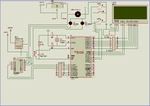
Please see the circuit. Untitled.png
 

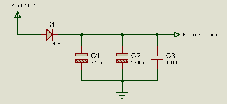
Do the "isolation" as I mentioned before:

1131641800_1354524741.png


Connect the 12VDC supply to point A. Connect point B to the circuit wherever you had labelled "+12VDC". To minimize diode voltage drop, you should use a schottky diode. However, a regular diode shouldn't be a problem.

Hope this helps.
Tahmid.
 

Point B will go into 7805 + supply, which will give +5vdc to controller??

Can i use this diode 1N4007 ???
 

Can you please tell me which diode can i use ???


Do the "isolation" as I mentioned before:

1131641800_1354524741.png


Connect the 12VDC supply to point A. Connect point B to the circuit wherever you had labelled "+12VDC". To minimize diode voltage drop, you should use a schottky diode. However, a regular diode shouldn't be a problem.

Hope this helps.
Tahmid.
 

Can you please tell me which diode can i use ???

You can use 1N4007 (or any of the 1N400X) if the current is <1A.
If current <3A, you can use any of the 1N540X.

Make sure you connected ULN2003 pin 8 to ground as it's a hidden pin in Proteus.
 
Last edited:

80series are not that ideal when it comes to driving inductive loads. this is as a result of their internal architecture where data/address has to make use of one path "von Neumann" Architecture. as this may result to error in terms of execution. the microcontroller may fetch wrongly when it is subjected to a strong EMI. so you have to be very careful when dealing with inductive loads; you will surely see the flaws of the 8051 micros!

so...
do a total isolation between the motor and the ground path of your circuit since it will not affect the operation of your design....as this will introduce noise looking at the power supply rails and thus will end up making the microcontroller to reset. also as suggested, do a proper power supply filtering.

ground the body of the crystal for a safer operation of the internal clock ciruit.
also increase the inductance of the ground by thickening the ground lines....if you have a vero board in your design then simply short unused copper line to the ground of your circuit.

above all you can shield your circuit from EMI generated by the motor....because this is a threat!

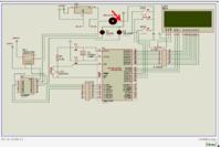
check out the image...

hope this helps
sequel...


- - - Updated - - -

80series are not that ideal when it comes to driving inductive loads. this is as a result of their internal architecture where data/address has to make use of one path "von Neumann" Architecture. as this may result to error in terms of execution. the microcontroller may fetch wrongly when it is subjected to a strong EMI. so you have to be very careful when dealing with inductive loads; you will surely see the flaws of the 8051 micros!

so...
do a total isolation between the motor and the ground path of your circuit since it will not affect the operation of your design....as this will introduce noise looking at the power supply rails and thus will end up making the microcontroller to reset. also as suggested, do a proper power supply filtering.

ground the body of the crystal for a safer operation of the internal clock ciruit.
also increase the inductance of the ground by thickening the ground lines....if you have a vero board in your design then simply short unused copper line to the ground of your circuit.

above all you can shield your circuit from EMI generated by the motor....because this is a threat!

check out the image...

hope this helps
sequel...


Status
Not open for further replies.

Similar threads

Part and Inventory Search

Welcome to EDABoard.com

Sponsor

Back
Top