Continue to Site

Welcome to EDAboard.com

Welcome to our site! EDAboard.com is an international Electronics Discussion Forum focused on EDA software, circuits, schematics, books, theory, papers, asic, pld, 8051, DSP, Network, RF, Analog Design, PCB, Service Manuals... and a whole lot more! To participate you need to register. Registration is free. Click here to register now.

Transistors to bypass mechanical switches

Status
Not open for further replies.

neazoi

Advanced Member level 6
Joined
Jan 5, 2008
Messages
4,123
Helped
13
Reputation
26
Reaction score
15
Trophy points
1,318
Location
Greece
Activity points
36,955
This is a silly question but I just want to make sure.
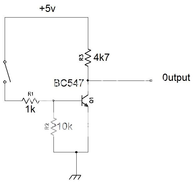
In the schematic provided, mechanical switches are used to set the logic levels on the buffers.

I am thinking of bypassing the switches with NPN transistors, to add the ability to electronically set the levels.
1. connect each NPN transistor collector to the pullup resistor (74244 buffer input)
2. connect each NPN transistor emitter to the ground.
3. Connect each mechanical switch to 5V directly and on each base of the transistors, in order to enable the transistor switch electronically.

Is this configuration correct?
 

Attachments

  • tr.GIF
    tr.GIF
    4.2 KB · Views: 108

Three variations on the theme....

View attachment 68214

I think the first case you propose is better for isolation purposes. I hope the component in the circle is a transistor and not a triac?
Why the attached solution won't work and why do you need the isolation resistor in the control?

* My control signal are positive pulses out of a 555 timer.
 

Attachments

  • 5v.GIF
    5v.GIF
    2.2 KB · Views: 109
Last edited:

If you use 555 to control, all three circuit work with it.
Last circuit is most simple.

Why the attached solution won't work and why do you need the isolation resistor in the control?

555toTrBase_.jpg
 

Thank you, I got that now.
However, It is not very clear to me how the rest of the circuits could be used. In the original schematic there are some pullup resistors, which I need to retain, since I also need the mechanical switch functionality. How your proposed circuits could be used with this?
 

You already find the solution. :-D
Transistors must bypass the switches, so here you find attached the final design. Full automatic control over the lines impose all switches must be open.
 

Attachments

  • Logic 1.GIF
    Logic 1.GIF
    11.7 KB · Views: 111

If we look the original schematic in post #1,
resistors are designed to provide a signal level of + V, when the switch is open.
This avoids indefinite "1" state because 74 244 input is not connected to digital "0" or "1" (gnd or +V)

If we look the circuit schematics in post #2,
input signals to 74244 are in all cases connected to
digital "0" or "1" ( gnd or +V ).
 

You already find the solution. :-D
Transistors must bypass the switches, so here you find attached the final design. Full automatic control over the lines impose all switches must be open.

Yes This was exactly what I have proposed in post #1, although I have not included the base resistor. This way the original behavior of the switches is not altered and the transistors behave like bypassed switches to the mechanical ones.

It is very clear to me how this works, I am not really confident of the circuits in post #2 to be honest, because I do not want to alter the value of the pullup resistor neither the position of the switches in the original circuit.

By the way, with an input pulse of +5V, what should be the value of the base resistor of the transistors, so as not to degrade the positive logic 1 in TTL series?
 
Last edited:

74LS family TTL
Outputs can sink up to 16mA , source about 2mA.

74HC and 74HCT family
Outputs can sink and source about 4mA if you wish to maintain the correct output voltage to drive logic inputs,
but if there is no need to drive any inputs the maximum current is about 20mA.

with general switch transistor ( hfe 150...400 )
I would use 10k...22kohm as base series resistor
 

Best way is to use haxfets i can recomened a cheap mosfet passing 400amps 50-60 volts with 0.003 ohms
a perfect switch. or scs silicon controlle switch.
 

invertor.jpg


try this schematic....it will work but another problem you may have is switch bounce ........
 

Status
Not open for further replies.

Part and Inventory Search

Welcome to EDABoard.com

Sponsor

Back
Top