Continue to Site

Welcome to EDAboard.com

Welcome to our site! EDAboard.com is an international Electronics Discussion Forum focused on EDA software, circuits, schematics, books, theory, papers, asic, pld, 8051, DSP, Network, RF, Analog Design, PCB, Service Manuals... and a whole lot more! To participate you need to register. Registration is free. Click here to register now.

transistor vbe-ib curve

Status
Not open for further replies.
VCE(sat)=1.5 V Collector-Emitter Saturation Voltage IC = 6A, IB = 600mA
VBE(sat)=2.0 V Base-Emitter Saturation Voltage VCE = 4V, IC = 6A
ref Fairchild https://www.fairchildsemi.com/datasheets/TI/TIP41B.pdf

This is silicon single stage transistor.
When saturated, the diode has a linear characteristic VI load line. Choose 0.7 for the threshold. Thus (1.5-0.7V)/0.6A= Rbe= 1¼Ω Thus the VI curve would be something like Vbe=0.7+Ib*1.25 for Fairchild

For ON Semi https://www.onsemi.com/pub_link/Collateral/TIP41A-D.PDF
Base−Emitter On Voltage
(IC = 6.0 Adc, VCE = 4.0 Vdc)
V BE(on)2.0 Vdc
using Ic/Ib=10
thus Rbe= (2-0.7)V / 0.6A = 2.17
Ω max

Finally ST
http://www.st.com/web/en/resource/technical/document/datasheet/CD00142950.pdf

Which has log-log curves for hFE=10
TIP41C.jpg

Given the specs are always rated at 25'C which only occurs for short pulses and/or water cooled, the Shockley effect drops the voltage with temperature rise so the Rbe has a wide effective tolerance.

EDIT
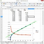
After digitizing the ST curves into a spreadsheetand calculating the slope for Rbe, the conclusion is that Vbe threshold assumption should be 0.8V for a linear load line and not 0.7V for this device.

The key is to note the Ic/Ib ratio standard is usually 10:1 for Vce saturation and Vbe sat curve is given for this ratio but plots Vbe vs Ic
Tip41C_.jpg
 
The curves on a datasheet are for a "typical" device that you cannot buy. Some devices are lower than the typical curve and other devices are higher. Buy a few thousand devices and measure all of them. Then you might be lucky to find some "typical" ones.

But maybe a huge manufacturer already took all the typical ones or maybe a bad production yield did not produce any.

Therefore you should design your circuit so that it works well with a minimum or with a maximum spec device.
Also don't forget that the temperature affects the Vbe.
 

Also note in my last graph the Rbe approaches 50Ohms for > 0.6A on Vbe or > 6A on collector , which means your source impedance must be similar or less if low voltage.

Knowing the source impedance of the driver and voltage allows one to determine the required series resistance to the necessary base current with limiting.

Understand that most power transistor switches require 10% base drive to saturate the collector to rated Vce(sat).

Ultra low Vce(sat) or low Rce(sat) transistors exist with 50:1 gain. You just need to need where to find them and can afford the higher cost. Intermediate ones using 15:1 to 30:1 for Vce(sat) specs.
 

Status
Not open for further replies.

Similar threads

Part and Inventory Search

Welcome to EDABoard.com

Sponsor

Back
Top