Continue to Site

Welcome to EDAboard.com

Welcome to our site! EDAboard.com is an international Electronics Discussion Forum focused on EDA software, circuits, schematics, books, theory, papers, asic, pld, 8051, DSP, Network, RF, Analog Design, PCB, Service Manuals... and a whole lot more! To participate you need to register. Registration is free. Click here to register now.

Transistor for Flourescent Ballast

Status
Not open for further replies.
ballast fluorescent lamps+transistor type

Kip:

Finally got around to reading the patent, too many other things in the way :(

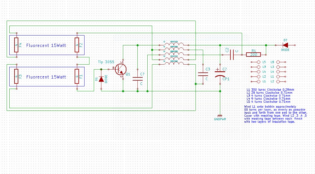
In the text, a NPN transistor 2N3055 is mentioned along with a few other components and some of their values.

How did the repair job turn out?

Tanuki
 

thin line ballast for rv

The repair guy bailed out, said he thought the coil was bad. Basically, though there are only eight components, it seemed beyond him.

I have a working model that uses two 15 watt tubes and one that uses one 8 watt tube.

If you tell me what to measure with a simple multi-meter under what conditions, I will do it right away.

The transistor in the patent is a metal cased transistor, not one of the flat black kinds.

Appreciate your continued interest.

Kip
 

thin lite ballast distributors, california

TIP3055 in a TO-247 package which has an isolated tab.

Use https://www.findchips.com to locate a supplier.
 

I too would rather spend a few bucks and repair or support my local radio/electronics shop to repair an item rather than unit replacement.
OOps! showing my age NO radio repair »service industry« in this day of disposable society..

2 of my 6 1989 Thin-Lite 716 Dual 15W Ballast fixtures have quit and one quits if i install new lamps.. replacement PC boards have failed faster than some of the originals.. Duhhh ;~}
I can read 185 thinlt C00406 etched into Q1 on expired :~{ replacement board

I would install a 2N3055 as listed in patent, except TO-3 metal housing

I installed NTE331 which specs very close to tip3055 package which lit both lamps but broke down quickly and now i have strobe fluorescence and high pitch cycle noise lots of HEAT.
biggest problem is delimitation of PCB cladding.. holding the Iron with my teeth old brittle boards don't do well trying to jerk out an IC.. LoL %~)

me Thinks I shall try replacement PCB but will remove them from heat sink aluminium backing and mount directly to lighting housing as was the original.. hopefully I will get better heat dissipation and longer life


I have 5 1988 Jensen model A8797 lamps which don't get nearly as hot and I have no problems as with the Thin-Lites.. wish they were still around i'd retrofit with their ballast

Transistor is twice the size of Thinlite.. circuit somewhat different. I can't find a thing on Jensen Aero as is printed on the PCB.. nor Jensen General Corp and their lamp line..

BTW; h**p://www.solarseller.com/thinlite_ballasts_replacement_dc_ballasts_thin_lite_.htm#ballast_models_197_to_1954
30 watt inverter ballast $19.ºº US for two F15T8 lamps.. good price all in all

h**p://www.st.com/stonline/products/literature/ds/4447/bul128.pdf STMicroelectronics has an interesting BUL series is designed for use in lighting applications and low cost switch-mode power supplies. TO-220 case h**p://www.st.com search keyword "BUL"
 

I have figured out how to get the tip3055 transistor to work and fix these stinking ballasts:

I also was having trouble with several of my ballasts. After studying this thread and carefully studying the PCB and understanding the circuit, I finally realized that their transistor is not in base/collector/emitter order, but rather backwards. So I reversed a tip3055 and it works like new. In order to do that, I simply twisted/flipped the PCB over after soldering the 3055 in and screwed just the transistor to the base aluminum. It's not pretty, but it works. I'm sure there is an equal transistor that has the order reversed (emitter/collector/base) and will make it more like new, but I only have the tip3055's and I haven't bothered to look anything else up.

Keep in mind that the original poster shows pictures of two different type ballasts; an older in the first photo, and later a different style PCB design in the later pics. The one this fixes is for the older type in the first photo. If not sure, look at what side the outer ferrite piece on the coil is relative to the transistor.

Fyi, one of my 6 ballasts is the newer type and it was the only one that was still working. I haven't studied it to know what the correct order is. But the older style ballasts' transistors all seem to be going bad at the same time.


I hope this helps someone!
 
Last edited:

Re: thin-lite transistor

2sd882 transistor is suitable.(if white wire is negtive)
and can replace as same conection
 

Hi all

After a lot of time and research I think I may have the answers you are looking for

---------- Post added at 01:20 ---------- Previous post was at 01:19 ----------

Hi there. I realize this thread is quiet old but I have recently had to investigate repair of these electronic Ballast units as fitted to Thin Light fittings in my Winne. I have reverse engineered the board and can answer some of your questions. Firstly being in the UK I prefer to refer to the board as an inverter because although it replaces the function of a mains ballast and does seem to be referred to commonly as an electronic ballast, it actually operates in a completely different way. The Inverter is a common designed with a small but clever variation. Instead of the normal transformer with three winding (Primary, Secondary and Feedback) the transformer has two extra windings of 8 turns each, which each connect to the ends of the dual tubes that are not linked together and supplies a low voltage to the heater filaments. The secondary high voltage output is connected across these two heater windings so the two ends of the series connected tubes have the High voltage applied across them. The ends of the tubes that are connected together are in series circuit with the feedback voltage output from the transformer and the base of the transistor. This will also produce a small voltage across the heaters. But the main purpose of this arrangement seems to be to inhibit the inverter if a tube fails or is removed. Without feedback the oscillator will stop oscillating.

I also noticed in earlier posts one reply suggested reversing his transistor made his board work, be careful with this one the original poster shows two boards one for the dual tube and one for the singe tube. The single tube circuit board is identical but mirrored so you would have to turn the transistor over for this board. The single tube board is also missing the unneeded windings on the transformer.

So conclusions.
I can confirm almost any high voltage general purpose NPN transistor will do the job, it is not critical. The Tip3055 is ideal, it has the voltage and power handling capabilities required with room to spare and as it is physically lager stays very cool. It is not necessary to isolate the tab when the transistor is mounted into a thin light housing as it is only at 12v and the casing is not otherwise earthed. If your casing is earthed or screwed into a mettle vehicle where contact is made with the chassis, then you will need to use a suitable insulator mounting kit that allows heat transfer or mount on a piece of insulation and use a separate heat sink. Or use a fully encapsulated equivalent.

Now the real problem. A lot has been said about why these units fail, It is not poor design. The two main reasons are normal wear to the insulation between the winding in the High voltage High frequency transformer. Sometimes you may hear a faint high pitched noise. This is caused by the windings in the transformer physically vibrating. This wears the enamel and eventually the insulation on the secondary high voltage output stage is likely to break down.
In fact if you have a unit that you can hear expect it to fail. This is by far the most common reason for these units to fail. Any resister or capacitor in this type of circuit that fails will normally be visibly damaged when it lets the smoke out. The transistor can fail but why should it most likely you will have to replace it because you broke it trying to get the rivet out that holds it to the case. That's why I had to replace mine.

Rewinding the transformer is not difficult (for a qualified person) and I have included the details of the number of turns on each winding on the attached circuit diagram.

Some tips for rewinding

Take the transformer apart carefully. Remove the tape from the graphite cor with a modeling knife and gently wiggle the two U shaped cores to get them out of the bobbin. Retain the two insulation discs that keep the two U shaped cores apart as you must put them back when you reassemble. Keep the windings as even and as tight as possible across the bobbin. The windings should go from one side all the way to the other side by spreading them out if required. The 350 turn secondary winding is the most critical and will require winding several layers back and forth, keep the layers tight together and even, because this coil has as much as 500v across it and if the two end of the winding came into close contact the insulation may fail, it is only good for about 150v. On mine each layer was 50 turns so the maximum difference between turns in contact with each other would be once across and back or 100 turns which is 140v. In reality spikes of up to 1000v can occur but the normal running voltage with the tubes struck is about 300v. A layer of masking tape between each separate set of windings will hold the coil in place reducing the physical movement of the windings and increasing the insulation between separate windings. Finish with insulating tape as tight as you can. Replace the two U shaped graphite cores with the two insulation disks and tape the exposed side together as it originally was. Leave your ends long enough to make it easy to refit in the board. Remove the lacquer from the ends and tin with a soldering iron. This will make it much easier to refit. If you have done a good job not only will your light work but it will be silent in operation.

I did mention two reasons for failure well the second I am afraid is quality. The secondary coil on my transformer was badly wound with bunching at one end this will cause excessive voltage differences between adjacent windings and vibration. Some of the soldering was messy and solder flux had not been removed this attracts moisture and may contain solder spatter causing short circuits or extra loading. So tidy things up if needed.

Finally this information is provided as information only and is not a recommendation to attempt a repair if you are not qualified to do so. There are very high voltages involved so do not attempt to work on any inverter if you are not sure you are qualified. If you do use any of this information it is at your own risk as I am not responsible for any damage or injury resulting from your use of this information. Also I cannot be sure of any changes that the manufacturer may have made between revisions of the boards so the accuracy of this information cannot be guaranteed.

 
P.W. that's nice work. Why not specify an isolated tab version of the transistor to eliminate the tab shorting concern? Polyester tape works best for transformers. Masking tape can become partially conductive.
 

Ahh Small Alteration to last post. In the first paragraph I said the Transformer has two extra winding of 8 turns each. It is actually Two extra windings of 4 turns each as shown on the Diagram attached. The size of the wire is not critical and the 0.71mm wire I used was slightly heavier than the original.

---------- Post added at 02:37 ---------- Previous post was at 02:26 ----------

Thanks KJ

I have found polyester tape doesn't hold/cushion the windings as well as masking tape and as it is not critical for insulation (The lacquer should do that) it works well. Of course you are correct polyester tape is what the manufactures use its just my personal preference. The Tip3055 is available in a fully encapsulated version which is probably the best choice but there are dozens of NPN bipolar transistors that will all work in this application as long as you are aware of the possible issue with the tab. So many people will have suitable transistors in their odds and ends box.

Regards Paul
 

Re: thin-lite transistor

i using also mje13003 please check on google this number and look at pic and veryfay of this part if look like sem the good other wise find more
normally using mje 13003 / 13005 / 13007
 

Hello p.w.stockwell:

I was impressed with your reverse-engineered dual 15 watt Thin-lite board circuit and commentary. It was quite thorough although re-winding a transformer is more than I would take on myself. You also made mention of the single 15 watt board: "The single tube circuit board is identical but mirrored so you would have to turn the transistor over for this board. The single tube board is also missing the unneeded windings on the transformer".

I have have several of the recessed style dual 15 watt Thin-lite model 716 fixtures (electrically the same as others) in my older (1984) motorhome. This fixture is very inefficient in light output due to having a non-reflective, cramped internal design; and a white semi-opaque cover. Over 50% of the light is lost as compared to the surface-mount Thin-lites. I want to convert these fixtures to using only a single 15 watt tube and compensate with better internal reflection and a clearer cover for greater efficiency. Using only 1.3 instead of the 2.6 amps of dual tubes will also reduce battery drain.

I am concerned about over-voltage using a single tube with this circuit, and I want to be sure to get it right and be reliable. Could I please get you to draw a single tube version of the dual-tube schematic shown on your post and used in some of the photos in this thread in order to help me convert mine over to using a single tube? Thank you in advance for any help you can provide.


Hi allusing a

After a lot of time and research I think I may have the answers you are looking for

---------- Post added at 01:20 ---------- Previous post was at 01:19 ----------

Hi there. I realize this thread is quiet old but I have recently had to investigate repair of these electronic Ballast units as fitted to Thin Light fittings in my Winne. I have reverse engineered the board and can answer some of your questions. Firstly being in the UK I prefer to refer to the board as an inverter because although it replaces the function of a mains ballast and does seem to be referred to commonly as an electronic ballast, it actually operates in a completely different way. The Inverter is a common designed with a small but clever variation. Instead of the normal transformer with three winding (Primary, Secondary and Feedback) the transformer has two extra windings of 8 turns each, which each connect to the ends of the dual tubes that are not linked together and supplies a low voltage to the heater filaments. The secondary high voltage output is connected across these two heater windings so the two ends of the series connected tubes have the High voltage applied across them. The ends of the tubes that are connected together are in series circuit with the feedback voltage output from the transformer and the base of the transistor. This will also produce a small voltage across the heaters. But the main purpose of this arrangement seems to be to inhibit the inverter if a tube fails or is removed. Without feedback the oscillator will stop oscillating.

I also noticed in earlier posts one reply suggested reversing his transistor made his board work, be careful with this one the original poster shows two boards one for the dual tube and one for the singe tube. The single tube circuit board is identical but mirrored so you would have to turn the transistor over for this board. The single tube board is also missing the unneeded windings on the transformer.

So conclusions.
I can confirm almost any high voltage general purpose NPN transistor will do the job, it is not critical. The Tip3055 is ideal, it has the voltage and power handling capabilities required with room to spare and as it is physically lager stays very cool. It is not necessary to isolate the tab when the transistor is mounted into a thin light housing as it is only at 12v and the casing is not otherwise earthed. If your casing is earthed or screwed into a mettle vehicle where contact is made with the chassis, then you will need to use a suitable insulator mounting kit that allows heat transfer or mount on a piece of insulation and use a separate heat sink. Or use a fully encapsulated equivalent.

Now the real problem. A lot has been said about why these units fail, It is not poor design. The two main reasons are normal wear to the insulation between the winding in the High voltage High frequency transformer. Sometimes you may hear a faint high pitched noise. This is caused by the windings in the transformer physically vibrating. This wears the enamel and eventually the insulation on the secondary high voltage output stage is likely to break down.
In fact if you have a unit that you can hear expect it to fail. This is by far the most common reason for these units to fail. Any resister or capacitor in this type of circuit that fails will normally be visibly damaged when it lets the smoke out. The transistor can fail but why should it most likely you will have to replace it because you broke it trying to get the rivet out that holds it to the case. That's why I had to replace mine.

Rewinding the transformer is not difficult (for a qualified person) and I have included the details of the number of turns on each winding on the attached circuit diagram.

Some tips for rewinding

Take the transformer apart carefully. Remove the tape from the graphite cor with a modeling knife and gently wiggle the two U shaped cores to get them out of the bobbin. Retain the two insulation discs that keep the two U shaped cores apart as you must put them back when you reassemble. Keep the windings as even and as tight as possible across the bobbin. The windings should go from one side all the way to the other side by spreading them out if required. The 350 turn secondary winding is the most critical and will require winding several layers back and forth, keep the layers tight together and even, because this coil has as much as 500v across it and if the two end of the winding came into close contact the insulation may fail, it is only good for about 150v. On mine each layer was 50 turns so the maximum difference between turns in contact with each other would be once across and back or 100 turns which is 140v. In reality spikes of up to 1000v can occur but the normal running voltage with the tubes struck is about 300v. A layer of masking tape between each separate set of windings will hold the coil in place reducing the physical movement of the windings and increasing the insulation between separate windings. Finish with insulating tape as tight as you can. Replace the two U shaped graphite cores with the two insulation disks and tape the exposed side together as it originally was. Leave your ends long enough to make it easy to refit in the board. Remove the lacquer from the ends and tin with a soldering iron. This will make it much easier to refit. If you have done a good job not only will your light work but it will be silent in operation.

I did mention two reasons for failure well the second I am afraid is quality. The secondary coil on my transformer was badly wound with bunching at one end this will cause excessive voltage differences between adjacent windings and vibration. Some of the soldering was messy and solder flux had not been removed this attracts moisture and may contain solder spatter causing short circuits or extra loading. So tidy things up if needed.

Finally this information is provided as information only and is not a recommendation to attempt a repair if you are not qualified to do so. There are very high voltages involved so do not attempt to work on any inverter if you are not sure you are qualified. If you do use any of this information it is at your own risk as I am not responsible for any damage or injury resulting from your use of this information. Also I cannot be sure of any changes that the manufacturer may have made between revisions of the boards so the accuracy of this information cannot be guaranteed.


Hi trueblue2k2

The Circuit is very similar to the twin tube version as it is built on essentially the same circuit board just mirrored. However the transformer is different, it does not have the extra windings to drive the heaters and the number of turns on the main windings may well be different. As I don't have a single tube version unfortunately I can't tell you what the windings are for that transformer.

In theory the capacitor C3 is limiting the current that can flow when the tubes have struck (a struck tube will allow a very large current to flow). So if you were to connect the base of the transistor directly to the junction of C2 and R1, without connecting through the tube heaters, then rearrange the tube connections so that the two tube heater windings on the transformer are connected to either end of a single tube it should work fine. However I would measure the current drain when operating and be prepared to reduce the value of C3 if it is high. Of course modification of this sort would be experimental so on your own head be it
 

Suggestion regarding rewinding the transformer: Plumbers PTFE tape is very cheap, a good electrical insulator, good at high temperatures and has just the right "stretchiness" to cushion and bind the windings together. It is also thin enough not to significantly increase the winding diameter.

Brian.
 

Good suggestion I have used loads of P.T.F.E tape from my days on the tools as a heating engineer. Your quite right P.T.F.E does have the correct properties its also cheap and readily available. also as there is no adhesive there is no solvent present that could affect other things.

Suggestion regarding rewinding the transformer: Plumbers P.T.F.E tape is very cheap, a good electrical insulator, good at high temperatures and has just the right "stretchiness" to cushion and bind the windings together. It is also thin enough not to significantly increase the winding diameter.

Brian.
 

Status
Not open for further replies.

Part and Inventory Search

Welcome to EDABoard.com

Sponsor

Back
Top