Continue to Site

Welcome to EDAboard.com

Welcome to our site! EDAboard.com is an international Electronics Discussion Forum focused on EDA software, circuits, schematics, books, theory, papers, asic, pld, 8051, DSP, Network, RF, Analog Design, PCB, Service Manuals... and a whole lot more! To participate you need to register. Registration is free. Click here to register now.

Transistor calculations ?

Status
Not open for further replies.

crazyjohn

Junior Member level 2
Joined
Dec 4, 2010
Messages
24
Helped
0
Reputation
0
Reaction score
0
Trophy points
1,281
Activity points
1,467
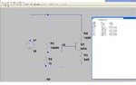
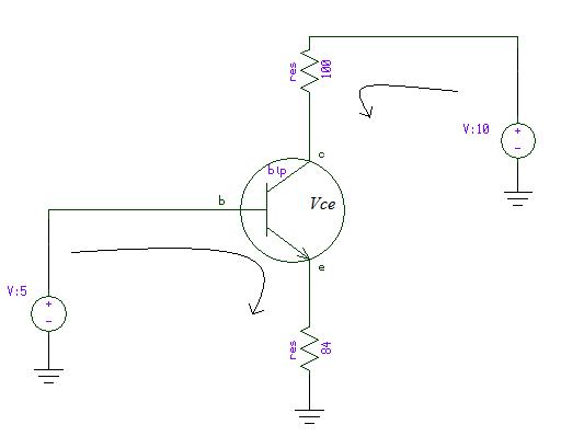
Couple of questions all related to bjt transistor biasing and calculating circuit variables ive added a screen shot of a spice simulation and the circuit variables it throws up.Wondering how the sim has calculated those variables ?

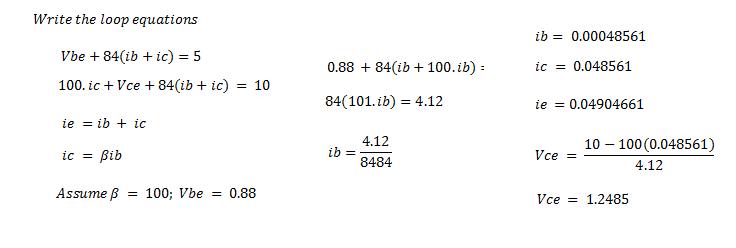
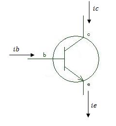
1. How is Ib calculated ?

2.How is Ic calculated ?

3.How is vce calculated ?
 

Attachments

  • transistor 1.JPG
    transistor 1.JPG
    130.8 KB · Views: 86

What is the beta and Vbe of the transistor that you used ?
 

The circuit consists of a lot of simultaneous equations - more than would appear to be the case on the circuit because the transistor model is fairly complex. Hfe, for example, is not constant but depends on Ic.

The simulator solves them iteratively, and numerically.
To solve it by hand you would tend to make approximations and simplifications.

Keith
 
Vbe is 0.88v hfe of the transistor is unknown.
 

Neither Vbe or hfe are fixed. They are one of the many many equations which make up the whole circuit. If the Spice model there will be a Bf value which is used in the calculation of beta.

With a few approximations it would be easy enough to get approximations to all the node voltages/currents.

Keith
 

You will not get the exact numbers by hand but in general you have a voltage divider in the base which
will give 5v to the base assuming the current it gives to the base is enough (10v/2000 or 5/1000 =5mA through the resistor)

with 5v to the base you will have 5-0.7=4.3v to the emitter so 4.3v/84=51mA emitter current.
The collector current will be the emitter current minus base current.

You have to find the collector current to calculate the hfe so you can just assume that the collector current is the same as the emitter current and find the hfe factor and from there you can find the base current.
There is also a resistor in the collector, if the emitter current * collector resistor (=voltage) is lower than the power supply voltage then vce will be about 10-(100*51ma)=4.9v.
If the voltage drop of the collector resistor is calculated to be more than the power supply voltage then the collector current will be limited by the collector resistor.

The numbers will not be accurate because there are many factors that change the parameters of the transistor but you will get an idea on the circuit currents.

Alex

*CORRECTION: the vce voltage will be 10-(100*51ma)-(84*51ma)=0.7v
 
Last edited:

Wow,Thank you for all yhe answers,these really helps.
 

Taking Vbe = 0.88 volts and lets assume beta = 100. beta = collector current / base current.
And also assume Vbe and beta are constant.

The base voltage is equal to 5V because of the voltage divider network. See the below two images.
And write the two loop equations and solve them, you will get Vce = 1.24 V

The emitter current will have a negative sign, because of the sign convention. (the direction of emitter current is opposite to the base and collector current)


Quote: The emitter current will have a negative sign, because of the sign convention. (the direction of emitter current is opposite to the base and collector current)

SV1437, are you really sure about that? Have a look on your own set of formulas.
 

Hi LvW,

See the figure below:
54_1293734359.jpg


You can see ib and ic flow into transistor and ie out of the transistor.

-sv
 

Thx very much.

Still have some problems trying to solve Ib.

How do you find a rough estimation of IB if you know IC but dont know the hfe of the transistor and to calculate hfe you have to know IB and Ic so what do you do to get a rough idea?

Is there any easy way of calculating the vbe ?
 

........and is " the direction of emitter current opposite to the base and collector current" ???
For my opinion ic and ie have the same direction - and this is also reflected in the formula ie=ib+ic (without any sign change).
 

The pspice simulator assumes all the currents(ib, ic, ie) are going into the transistor. So if you want your answers to match to the values given by simulator, then you should take the negative sign for ie. See the attached thumbnail in the first post.
 

Thx very much.

Still have some problems trying to solve Ib.

How do you find a rough estimation of IB if you know IC but dont know the hfe of the transistor and to calculate hfe you have to know IB and Ic so what do you do to get a rough idea?

Is there any easy way of calculating the vbe ?

I am a bit confused as to whether the question is about how to solve an arbitrary set of equations (which a simulator easily does) or how to do a design. If I assume the latter then in general you assume Vbe is something like 0.7V unless you have some reason to assume it is something else to start with.

Normally you would be designing for some specification. The output drive required and maybe the gain would determine the collector resistance and current. You must have some idea of the hfe, although you design will have to be tolerant of a reasonable range of hfe.

So, you have Vbe, Ic, hfe and therefore Ib defined. You would choose the base resistor divider current so it is not significantly affected by Ib - say 10 times Ib. So you can now pick Re.

You can then manually correct the calculations knowing Ib if you want.

To look at a complete circuit and say how is it all calculated is probably the wrong way to look at things.

Keith
 

For a rough estimation, you can assume a fixed B and even a fixed Vbe value. For the present circuit, you'll get near to the exact solution this way.

Wondering how the sim has calculated those variables ?
The equations are nonlinear and can only be solved by iteration. So, the simulator is using the same method you would apply for an exact solution:
- Make a first guess, e.g. for B and Vbe, then solve the remaining set of linear equations
- Get more exact values for B and Vbe from the transistor model, respectively the datasheet, solve the equations
- Repeat until the specified accuracy is achieved
 

Status
Not open for further replies.

Similar threads

Part and Inventory Search

Welcome to EDABoard.com

Sponsor

Back
Top