eengr
Member level 4

Hi
I am trying to interface an O2 Electrochemical sensor on my board.
I have used potentio-static & transimpedance amplifier configuration.
I have tried to use what I found in number of application notes online.
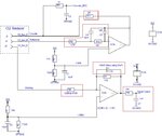
My circuit is as shown in the picture

Rail bypass caps of 100nF & 1uF not shown in this circuit but they are present on actual board
I am not an expert in circuit design so still learning.
The sensor requires bias boltage of apprx -300mV to -600mV. So working electrode is apprx 382mV less than Reference Electrode
I chose R3&R4 to get 1.777VDC as my bias voltage for Reference electrode
I chose R1 &R2 to get 1.395VDC as my bias voltage for Workingelectrode
Rgain (R7) (I used as 1K here although I would like to be bit more Gain but I could live with 1K for now if I could get this circuit to stable condition.)
Rload (R6) - I was advised by manufactuerr to use 100R to 470R. So I have tried both values and in between
I am not entirely sure how best to calculate C(feedback) (C6) but I saw one application note online which gave a formula like

In my case manufacturer does not provide the value of (C_s), but I have found in same application note & one from Alphasense that for electrochemical sensors the Capcitance of Working Electrode could be from 1mF to 300mF
Regarding OPAMPs I have tried MCP6032 which has GBW of 10kHz
I have also tried AD8607 which has GBW of apprx 350kHz
For MCP6032 I first used 100nF (C_feedback) (C6). & then I found the above formula and decided to use 10uF
For AD8607, I have used 100nF only
I have not got a slightest clue how the feedback Caps & Resistor values are chosen for potentiostatic side (R9, C4, R10, C5) & also the resistor R11. I just used what I found in some circuits online. (Not a great way to doing but I could not find a step by step guide or design notes)
All component values are as shown in the picture.
I have stability issues where my rails keep collapsing and I don't see my DC reference levels as expected.
Could someone please guide me in how to tackle this problem. What is the usual way of selecting the suitable component values for this kind of application to fix the oscillation problem.
As soon as circuit goes unstable, it starts taking to much current at 3.3V supply and does not allow me to take any meaningful measurements to start troubleshooting.
I am trying to interface an O2 Electrochemical sensor on my board.
I have used potentio-static & transimpedance amplifier configuration.
I have tried to use what I found in number of application notes online.
My circuit is as shown in the picture
Rail bypass caps of 100nF & 1uF not shown in this circuit but they are present on actual board
I am not an expert in circuit design so still learning.
The sensor requires bias boltage of apprx -300mV to -600mV. So working electrode is apprx 382mV less than Reference Electrode
I chose R3&R4 to get 1.777VDC as my bias voltage for Reference electrode
I chose R1 &R2 to get 1.395VDC as my bias voltage for Workingelectrode
Rgain (R7) (I used as 1K here although I would like to be bit more Gain but I could live with 1K for now if I could get this circuit to stable condition.)
Rload (R6) - I was advised by manufactuerr to use 100R to 470R. So I have tried both values and in between
I am not entirely sure how best to calculate C(feedback) (C6) but I saw one application note online which gave a formula like
In my case manufacturer does not provide the value of (C_s), but I have found in same application note & one from Alphasense that for electrochemical sensors the Capcitance of Working Electrode could be from 1mF to 300mF
Regarding OPAMPs I have tried MCP6032 which has GBW of 10kHz
I have also tried AD8607 which has GBW of apprx 350kHz
For MCP6032 I first used 100nF (C_feedback) (C6). & then I found the above formula and decided to use 10uF
For AD8607, I have used 100nF only
I have not got a slightest clue how the feedback Caps & Resistor values are chosen for potentiostatic side (R9, C4, R10, C5) & also the resistor R11. I just used what I found in some circuits online. (Not a great way to doing but I could not find a step by step guide or design notes)
All component values are as shown in the picture.
I have stability issues where my rails keep collapsing and I don't see my DC reference levels as expected.
Could someone please guide me in how to tackle this problem. What is the usual way of selecting the suitable component values for this kind of application to fix the oscillation problem.
As soon as circuit goes unstable, it starts taking to much current at 3.3V supply and does not allow me to take any meaningful measurements to start troubleshooting.