Continue to Site

Welcome to EDAboard.com

Welcome to our site! EDAboard.com is an international Electronics Discussion Forum focused on EDA software, circuits, schematics, books, theory, papers, asic, pld, 8051, DSP, Network, RF, Analog Design, PCB, Service Manuals... and a whole lot more! To participate you need to register. Registration is free. Click here to register now.

Transformerless Power Supply Help

Status
Not open for further replies.

Mithun_K_Das

Advanced Member level 3
Joined
Apr 24, 2010
Messages
899
Helped
24
Reputation
48
Reaction score
26
Trophy points
1,318
Location
Dhaka, Bangladesh, Bangladesh
Activity points
8,252
Help required in Transformer less power supply. I use this power supply for a small product where load is only 50mA at 5V. Without load voltage is around 5.6V and with load 4.8V. Circuit works fine only one problem happens each time.
The zener diode. Zener diode damages frequently. Specially when a spike comes.
02.png
How can I improve this circuit so that zener diode become stable. Also size of the total circuit is a matter. I can not use many components.

*** Circuit must be with common phase. So it may be looking odd but it works the best with few components.
 

If you review similar circuits published at Edaboard, you'll notice that most have a current limiting resistor, e.g. 100 ohm/1W in series with the capacitor. It's absolutely required to limit inrush current and transients.
 
  • Like
Reactions: ycsoh

    ycsoh

    Points: 2
    Helpful Answer Positive Rating
If you review similar circuits published at Edaboard, you'll notice that most have a current limiting resistor, e.g. 100 ohm/1W in series with the capacitor. It's absolutely required to limit inrush current and transients.

Yes, I used that before. Result was resistor also get damages. And the circuit then do not work with inverter with square wave or modified square wave output. So elemenated that series resistor.
 

Helpless case. The "capacitor drop" power supply can't work with square wave or similar input voltage if it's designed for sine, and won't work reliably without the series resistor.

Go for transformer, regular flyback SMPS or possibly non-isolated buck converter.
 

I don't think that NTC solves the problem. For 50 mA output, you need 100 mA AC input current in half-wave rectifier circuit. With 2.2 µF capacitor (about 1.5 µF is the minimal value) and modified square wave, you get about 20W losses in series resistor. Without series resistor, peak current would rise to > 10A.
 

Really you need a bridge rectifier ( 4 x 1N4007) to maximise the current (x2) followed by a large zener ( 1W ), and as above, a current limiting res in series with the cap, say 220E, 5W. At 230Vac the cap needs to be smaller, say 1uF, this will give you ~ 72mA, which is 400mW in a 5v6 zener, and 1.2W in the 220E res, so 3W should be OK here.
You also need 1000uF cap across the zener to limit the V ripple to 350mV pp.
 
I don't think that NTC solves the problem. For 50 mA output, you need 100 mA AC input current in half-wave rectifier circuit. With 2.2 µF capacitor (about 1.5 µF is the minimal value) and modified square wave, you get about 20W losses in series resistor. Without series resistor, peak current would rise to > 10A.

Can you please give me any tutorial of the calculation of Transformerless Power Supply? As far as I know to calculate the current with Xc of capacitor. But is there any other calculation? Also how can I get the value of Inrush current?
 

Inrush current = Vpk ( 325V) / R series ( 220E) = 1.5A pk decaying to steady state after the 1st half cycle, peak inrush occurs if ckt switched on at peak mains voltage...
 

OK. Then if I use a TRIAC in parallel with the zener diode will it help?

Capture.PNG

I tried with using a shunt regulator with Transistor and Zener diode. That case, output voltage is ok but current is too much low.
 

Hi,

TRIAC concept comes to protect the circuit from spikes.
Yes, usually for unexpected high voltage spikes
You usually don't have high dV/dt at a sinewave. Thus the triac will be activated only in some error situations.

But with a square wave they are quite expectable: twice per fullwave.
Do you really want the triac to be activated that often? And how do you think the power supply can work properly when the triac "short circuits" the signal?

It seems you work with a simulation tool. Thus you should be able to find out on your own about voltages, currents and overall functionality.

Klaus
 

How about shifting the zener to the right side of the rectifier diode? To reduce the surge current, use two 4.7uF (or, perhaps you can use two2.2uF but reduce the protection diode to 33K or so) caps in series (each with a 47K protection resistor). You can also use a bridge rectifier and reduce the capacitor value further.
 

The current passing through C3 has to be reasonably symetrical so moving the Zener to the right side of the rectifier will simply result in C3 charging to DC. It would work if a bridge rectifier was used so the polarity across C3 alternates.

I fear there is no simple and safe (assuming an isolated load) solution to the problem except adding the series resistor as already recommended.

Brian.

Series resistor is expected and that is ok. But problem is if supply voltage become low, output falls. Also that resistor get damage after few months of use.
 

Hi,

Naïve suggestion:

Could a BJT or Mosfet be used to replace the undesired series resistor (for the 500uF capacitor, I'm assuming) and be soft started via a parallel slow-rising circuit to turn it on to limit the inrush current? Somehow?

I guess not without a handful of PCB-hogging additional components.
 

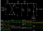
By including two smoothing capacitors (with resistor in between), it reduces stress on components. Smaller watt values can be used.

Notice the 500 uF capacitor is now two lesser values.
R1 and R2 can be less than 1W.
My simulation leaves the zener diode unconnected to show volt levels without it.

Inrush current is 4 A for under 1 mSec, which ought to be tolerable.

cap drop 230VAC diode-bri filter=2 resis 2 caps 5Vdc load 50mA.png
 
Hi Brad, how many volts on C2? what is the power in R1, R2 ...?

- - - Updated - - -

you must always have a zener on the output to limit Vrise ( on the caps ) if the load is taken away ....
 

Status
Not open for further replies.

Similar threads

Part and Inventory Search

Welcome to EDABoard.com

Sponsor

Back
Top