thannara123
Advanced Member level 5
Pleas discuss A up to 500 watt transformer-less Inverter's design structure , advantage ,disadvantage etc ..
I am planning to make it ?
I am planning to make it ?
Follow along with the video below to see how to install our site as a web app on your home screen.
Note: This feature may not be available in some browsers.
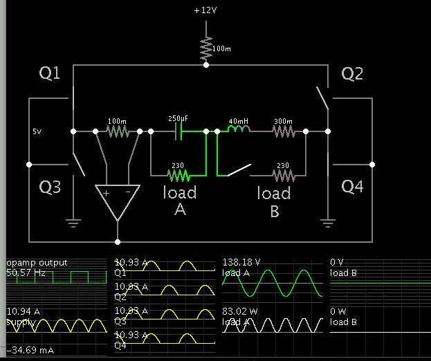
Very true.I doubt however that using a single inductor boost topology (either conventional or resonant) is a good idea. The basic problem is that the 12:230 or 12:300 boost ratio also multiplies the switched power (Imax*Vmax) by a large factor.
A very famous paper was posted once by HP (~1982 I think) showing the same thing but they designed a variable inductor (varied with applied DC) to give a variable resonance freq in the power ckt with constant applied freq - this worked very well and would be great for your ckt...!