Continue to Site

Welcome to EDAboard.com

Welcome to our site! EDAboard.com is an international Electronics Discussion Forum focused on EDA software, circuits, schematics, books, theory, papers, asic, pld, 8051, DSP, Network, RF, Analog Design, PCB, Service Manuals... and a whole lot more! To participate you need to register. Registration is free. Click here to register now.

topology optimization

Status
Not open for further replies.

ravi.2k17

Advanced Member level 4
Joined
Sep 30, 2019
Messages
111
Helped
0
Reputation
0
Reaction score
1
Trophy points
18
Activity points
874
hi all,

I am going to connect different types of sensors (PIR, radar microwave, photoelectric) with an Arduino. I have 10 rooms in my building (2 floors) where in each room approx 4 sensors will be installed thus making it 40 sensors all should be connected to same Arduino. If I use simplest topology, there will be direct connection of each sensor to my Arduino involving total 40X3=120 wires terminating to Arduino creating lots of cable mess. I though there should be some provision to connect all 4 sensors of one room to a single point from there only 3 wire should terminate to Arduino. is there a way to make this connection in multi level tree topology?

I thought of using i2c bus for that but i am not sure
1) if this can be done for distant connections (approx. 30 meter between sensors and Arduino).
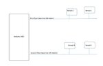
2) if we can create multi level tree topology, where each room's sensors' are connected to single common point and from there each rooms common point is connect per floor's root node and at last all floor's root node are connected to Arduino. some thing as below.

1605211661172.png


this way i can reduce the wiring significantly. what are my options?

thanks
 

Hi,

I2C = IIC = inter IC communication. Designed for onboard communication between different ICs.
Nowadays it's used for short distance communication between different boards/devices.
But it's not meant for several meters of distance.
Forget about I2C for room to room or even floor to floor communication.

Use something like RS485 or other differential bus for wiring and a sensor protocol like Modbus.

For better assistance we need more details, like data rate in bits/second, and how often you need to request data from a sensor.
And we need information about current consumption of the sensors.

Klaus

pir sensor hc-sr501 --- total 10 in different rooms --- current consumption 65mA each
RCWL-0516 Microwave Radar Sensor --- total 12 in different rooms --- current consumption 3mA each
DHT22 temperature and humidity --- total 4 --- current consumption 1.5mA each
YHDC SCT-013-000 Current Sensor --- total 1 for main AC line
38KHz Infrared IR Receiver Sensor Module --- total 4 outside building --- current consumption 5mA each

>>>>For better assistance we need more details, like data rate in bits/second
how can i calculate data rates bits per second for all the sensors?

>>>how often you need to request data from a sensor.
as they are for intrusion detection I would like to query every 1/2 second each sensor.

>>>And we need information about current consumption of the sensors.
current consumption are shown above. do you want me to calculate aggregated consumption by using current X total sensors formula?

With optimization my intention is to reduce the cabling cost and maintenance but at the same time system topology should not go too complex.

thanks
 

Hi,

31 sensors.
--> can some sensors in close proximity be joined (to one "communication node" = microcontroller). Which ones?

Modbus RTU (at first sight) needs about 25 byte times per request+response+2x silent
this gives a total of 31nodes x 25bytes/node x 11 bits/byte x 2/second = 17kbits/second

700mA over a standard twisted pair at 5V will cause too much voltage drop.
Thus consdier either
* decentral power supplies
* higher voltage on a twisted pair (24V, 48V) with decentral step down.

Klaus

I will discuss over these points later. But first I want to confirm if modbus, rs485 or CAN protocol are good for star/tree topology?
 

Hi,

I don´t recommend star topology at all for those wide and lenghty network.
Maybe it works with a low data rate .... but without knowing data rate at all .. all you can do is trial and error method.
And in case it works you need to hope that nobody changes any wiring later. .

Klaus
 

Hi,

I don´t recommend star topology at all for those wide and lenghty network.
Maybe it works with a low data rate .... but without knowing data rate at all .. all you can do is trial and error method.
And in case it works you need to hope that nobody changes any wiring later. .

Klaus

if we can not use star topology. then i have only two options left.

1) terminate all sensors connection to Arduino making jungle of wires on one side. which is the simplest for me to code and maintain. but trying to refrain using this as much as possible.

2) create a common main base line bus and connect each sensor to the same bus. terminating the main bus to Arduino as below. i though of using rs485 but it has a limitation of max 32 devices on the common line. so what can i do in this case? plz see the attachment
 

Attachments

  • Untitled.jpg
    Untitled.jpg
    13.6 KB · Views: 146

Hi,

your picture is not clear. It does not show cable length thus it´s not clear whether this is star wiring or not.
You still can use one bus per floor...If you use CAT.5 cables you may use multiple busses in one cable.

Why is the 32 devices limitation a problem? You don´t have more than 32 devices.

You said you want to talk "later" about joining sensors. I think it´s time for it now, because it has impact whether the one solution is possible or not.

Klaus
as you said earlier, start topology is not a good option here, hence i dropped that idea and started concentrating on main bus line architecture where all the sensors will be connected to same bus. how many bus (either 1 for both floors are 2 one for each floor depends on you suggestion).

below is the pic for one base line per floor. but can we have two base lines with same Arduino? does this 32 constraint applies for both the buses or for each bus?
i am just curious about scalability perspective. currently i have only 31 by the way. I have just given a rough diagram not the exact one. please let me know if you need more info in that.

>>>can some sensors in close proximity be joined (to one "communication node" = microcontroller). Which ones?
yes we have around 4-5 sensors in closed proximity. but can they be joined? could not understand this part.


moreover i can think of single base line for both the floors but the total length may increase to 50 meter appox in that case. is it a good idea ???
 

Attachments

  • Untitled.jpg
    Untitled.jpg
    23.8 KB · Views: 128

Hi,

Limit of 32 is per bus. You may have many base lines as you like.
And if you give each sensor a different address you may use one UART and AND all RO of the RS485 ICs. With max of 255 sensors.

To join sensors you need a microcontroller. Each sensor that communicates via Modbus needs a microcontroller anyways.

50m is no problem for RS485 with correct cables, and correct termination.

Klaus
 

32 bus devices is limitation of industry standard transceivers with minimal specification.Transceivers with better spec support up to 256. You should consider that an arbitrary multi node topology can't use impedance matching termination. Respectively it's restricted to low baud rates because the signal reflections must decay after each bit.
 

Hi,

Limit of 32 is per bus. You may have many base lines as you like.
And if you give each sensor a different address you may use one UART and AND all RO of the RS485 ICs. With max of 255 sensors.

To join sensors you need a microcontroller. Each sensor that communicates via Modbus needs a microcontroller anyways.

50m is no problem for RS485 with correct cables, and correct termination.

Klaus


hi klaus,

now i need to understand the wiring of the whole setup as i could not get anywhere.
1) how to connect two base lines to Arduino ? any shield, interface etc ? which Arduino pins i can use for each line?
2) how to connect each sensor to base line ?
3) which microcontroller are you talking about for sensor connection ?
4) what cable would be best for the wiring?
5) how Arduino code will change in this case?


i have done exercise for connecting one pir sensor to Arduino using max485 breakout board as a transmitter and receiver but that seem to be a point to point connection.
what will change here with that respect.

in attached pic there are 4 points where i need to understand the connection/interfacing.


thanks
 

Attachments

  • Untitled.jpg
    Untitled.jpg
    27 KB · Views: 144

Hi,

Hardware:
Arduino has UART. You connect the TxD --> DI of a RS485 transceiver chip. It has differential bus input/outputs. Connect these to a diff pair of a cable.
This cable forms a non star long distance bus with up to 32 sensors.

You may use another RS485 chip, to generate another bus (maybe for the other floor). You may connect DI of the transceiver in parallel to the other DI to the same TXD of the Arduino. (As long as all sensors get different addresses).
This forms another non star long distance bus with up to 32 sensors.

You may add others busses this way.
Connect all DE of the transceiver cips in parallel to a arduino Driver_enable pin of your choice.
Connect all RE of transceivers in parallel to GND

Use an AND gate and connect each transceiver's RO pin to individual AND input.
Connect the AND output to RxD of the arduino.
Connect all unused AND inputs to VCC.

If you have sensors with RS485 interface and Modbus protocol you may connect them directly to the bus as you like. Mind: the branches need to be short to the true bus, individual addresses, proper termination on each bus end.

If your sensors don't have RS485/modbus .... you need a device (usually a microcontroller, another arduino...) to "translate" between RS485 and sensor interfaces. These are called "bus slaves" and may join several sensors in close proximity.

******
Software: Modbus protocol should be available as master and slave in the arduino IDE.

Klaus

I have made below initial circuit diagram based on your suggestion
it has two base lines for first and ground floor. as of now i have connected one sensor per base line to the far end. for ttl to rs485 conversion (PIR sensor hc-sr501) i have connected another max484 board as transmitter. could you please review this? diagram attached
 

Attachments

  • Untitled.jpg
    Untitled.jpg
    307.8 KB · Views: 161

Hi,

There are many mistakes. Basic mistakes.
* not knowing what "bus" means
* not knowing what termination means
* more than one driver ON at the same time
* no yet read/understood about modbus protocol .... knowledge about protocol and addressing at all.

I guees the project is over your head. My recommendation. Take your time and learn step by step or look for a partner with according knowledge.

Klaus

you are absolutely right. I tried to directly jump to implementation without having proper knowledge of modbus protocol.
to fill the gap, i went through couple of documents and videos about this protocol. finally got an idea. I came to know that "Daisy chain" wiring should used for modbus. and approx 120 ohm registers needs to be added between the differential lines on two ends. more over all sensors needs to be configured unique ID before we can use them in the network. i will take small steps to understand this protocol by implementing simple master slave communication between two Arduinos first of all.

>>>> If your sensors don't have RS485/modbus .... you need a device (usually a microcontroller, another arduino...)

as you know that all my sensors (eg HC-SR501 Pir Motion) are not Modbus compliant. hence we need some sort of converter.
can MAX485 work here as Modbus slave ? if not, which microcontroller i can use for making my TTL sensors to Modbus compliant? another way is to use other Arduinos and connecting them to bus as Modbus slaves. but i do not want to do that.


thanks
 

Hi,

Well done so far.
MAX485 has nothing to do with modbus.
You may use modbus without MAX485 ... and you may use MAX485 without modbus.
One is a (hardware) interface (specification) .... the other is a protocol.

Protocol is like a language. In most cases a microcontroller is used.

Klaus
 

Hi,

Well done so far.
MAX485 has nothing to do with modbus.
You may use modbus without MAX485 ... and you may use MAX485 without modbus.
One is a (hardware) interface (specification) .... the other is a protocol.

Protocol is like a language. In most cases a microcontroller is used.

Klaus

which one is the simplest ans cheapest micros controller can be used for this purpose.
Atmega328P seems costly if needs to be used for each sensor.
 

Hi,

Almost any microcontroller will do. I recommend one with UART periferal inside.
As already mentioned earlier, you may join several sensors in close proximity to one microcontroller (= one bus node = one modbus slave)

Klaus
 

Status
Not open for further replies.

Similar threads

Part and Inventory Search

Welcome to EDABoard.com

Sponsor

Back
Top