Continue to Site

Welcome to EDAboard.com

Welcome to our site! EDAboard.com is an international Electronics Discussion Forum focused on EDA software, circuits, schematics, books, theory, papers, asic, pld, 8051, DSP, Network, RF, Analog Design, PCB, Service Manuals... and a whole lot more! To participate you need to register. Registration is free. Click here to register now.

To display a square on monitor ( Verilog vga Basys 2 board )

Status
Not open for further replies.

sukanya28

Junior Member level 2
Joined
Oct 1, 2014
Messages
23
Helped
0
Reputation
0
Reaction score
0
Trophy points
1
Visit site
Activity points
213
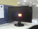
Hi, I wish to display a red square through my verilog code but a bar is getting displayed, also I am not able to change my right co-ordinate. Why is it so?? Please help !!

Code :

Code:
module vga_sq(input wire clk,reset,
output wire hsync,vsync,
output [2:0] red, // three bit signal to drive color red
output [2:0] green, // three bit signal to drive color green
output [1:0] blue, // two bit signal to drive color blue (human eye is less sensitive to color blue)
output reg video_on);
	 

// defining constants
localparam HD = 800; // horizontal display area
localparam HF = 56; // front porch (right border)
localparam HB = 64; //right porch (left border)
localparam HR = 120; // horizontal retrace
localparam VD = 600; // vertical display area
localparam VF = 37; // front porch (bottom border)
localparam VB = 23; // back porch (top border)
localparam VR = 6; // vertical retrace
localparam h_end = 1040; // total horizontal timing
localparam v_end = 666; // total vertical timing
//localparam sq_size = 20; // size of square
localparam sq_x_l = 390; //  left coordinate of square
localparam sq_x_r = 410;
localparam sq_y_t = 290;     
localparam sq_y_b = 400;

//horizontal and vertical counter

reg [10:0] h_count_reg,v_count_reg ; // registers for sequential horizontal and vertical counters
reg[10:0] h_count_next , v_count_next;
//reg v_sync_reg , h_sync_reg ;
//wire v_sync_next , h_sync_next ;
reg v_sync_next , h_sync_next = 0 ;


always @ ( posedge clk , posedge reset)
if (reset)
begin
v_count_reg <= 0;
h_count_reg <= 0 ;
//v_sync_reg <= 1'b0;
//h_sync_reg <= 1'b0;
end
else
begin
v_count_reg <= v_count_next;
h_count_reg <= h_count_next;
//v_sync_reg <= v_sync_next ;
//h_sync_reg <= h_sync_next ;
end

// horizontal and vertical counters
always @(posedge clk) 
begin
if(h_count_next < h_end-1)
begin
			
h_count_next <= h_count_next + 1;
end
else 
begin
h_count_next <= 0;
			
if(v_count_next < v_end-1)
v_count_next <= v_count_next + 1;
else
v_count_next <= 0;
end
end

// horizontal and vertical synchronization signals
always @(posedge clk)
if(h_count_reg < HR)
h_sync_next <= 1;
else
h_sync_next <= 0;
			
	
//VSync logic		
	
always @(posedge clk)
if(v_count_reg < VR)
v_sync_next <= 1;
else
v_sync_next <= 0;

assign hsync = h_sync_next;
assign vsync = v_sync_next;


reg h_video_on,v_video_on; // these registers ensure that the display signals are sent only when the pixels are within the display region of the monitor.
//horizontal logic

always @(posedge clk) 
if((h_count_reg >= HR + HF) && (h_count_reg< HR + HF + HD))
h_video_on <= 1;
else
h_video_on <= 0;
			
	
//Vertical logic
	
always @(posedge clk)
if((v_count_reg >= VR + VF) && (v_count_reg < VR + VF+ VD))
v_video_on <= 1;
else
v_video_on <= 0;

always @(posedge clk)
if(h_video_on && v_video_on)
video_on <= 1;
else
video_on <= 0;


reg [9:0] pixel_x,pixel_y; // registers to describe current position of pixel within display area.

always @(posedge clk)
if(h_video_on)
pixel_x <= h_count_reg - HR - HF;
else
pixel_x <= 0;

always @(posedge clk) 
if(v_video_on)
pixel_y <= v_count_reg - VR - VF;
else
pixel_y <= 0;

//color output
reg [7:0] coloroutput; // 8 bit register which describes which color has to be displayed but only when video_on signal is turned on.

always @(posedge clk)
if(~video_on)
coloroutput <= 0;
else
begin
if((pixel_x > sq_x_l && pixel_x < sq_x_r) && (pixel_y > sq_y_t && pixel_y < sq_y_b ))
coloroutput[7:5] <= 3'b111;
else 
coloroutput [4:0] <= 5'b00000;
end


assign red = coloroutput[7:5];
assign green = coloroutput[4:2] ;
assign blue = coloroutput[1:0] ;


endmodule


Code Verilog - [expand]
1
2
3
4
if((pixel_x > sq_x_l && pixel_x < sq_x_r) && (pixel_y > sq_y_t && pixel_y < sq_y_b ))
    coloroutput[7:5] <= 3'b111;
else 
    coloroutput [4:0] <= 5'b00000;


What do you think that does? And while you are answering that ... pay close attention to which bits of coloroutput you are writing to.
 
As I wish a red colored square, therefore, I assigned these 3 MSBs as 1.
And regarding this statement "if((pixel_x > sq_x_l && pixel_x < sq_x_r) && (pixel_y > sq_y_t && pixel_y < sq_y_b ))" ,when I change y coordinates,changes in vertical coordinates of square are visible but the same is not the case with x coordinates.
 

Well obviously. Couple of things. 1) You write it as if you still have flashbacks to writing C. 2) amusingly enough in the C equivalent you would get the same problem.

I repeat: pay close attention to which bits of coloroutput you are writing to.

I could spell it out for you, but then you don't learn to fix your own stuff in the future. ;) Speaking of future, could you use

Code Verilog - [expand]
1
2
3
4
5
6
7
8
9
instead of code tags in the future? code sorta works, but syntax tags makes it much more readable. Pretty colors AND it helps you in getting your indentation right.
 
[COLOR="silver"][SIZE=1]- - - Updated - - -[/SIZE][/COLOR]
 
I'll put it another way:
 
[I]"As I wish a red colored square, therefore, I assigned these 3 MSBs as 1. "[/I]
 
And what do you do with the other 5 bits at that point in time? If you don't think it is important at that point in time, what hardware do you think the synthesizer is going to infer for you?

 
Thank you Mr. Fibble. The code is working now.

20141014_122835.jpg


Code Verilog - [expand]
1
2
3
4
5
6
7
8
9
10
always @(posedge clk)
if(~video_on)
coloroutput <= 0;
else
begin
if((pixel_x > sq_x_l && pixel_x < sq_x_r) && (pixel_y > sq_y_t && pixel_y < sq_y_b ))
coloroutput[7:5] <= 3'b111;
else
coloroutput[7:0] <= 8'b00000000;
end


Progress! :)

And the full hint is to use this as well: coloroutput[7:0] <= 8'b11100000;

It specifies more fully what you intend, and it gives the synthesizer less room to infer logic that you didn't want.
 
To change position of square on monitor with a push button (VGA verilog Basys2 board)

Hi, I have displayed a square on monitor with vga controller. Now I want to change its position ( left/right ) by incorporating a push button but the code is not working. Also when I simulate the testbench, button pin 'btn' is not getting simulated. I have attached testbench and .ucf file too. Please help !!


Code Verilog - [expand]
1
2
3
4
5
6
7
8
9
10
11
12
13
14
15
16
17
18
19
20
21
22
23
24
25
26
27
28
29
30
31
32
33
34
35
36
37
38
39
40
41
42
43
44
45
46
47
48
49
50
51
52
53
54
55
56
57
58
59
60
61
62
63
64
65
66
67
68
69
70
71
72
73
74
75
76
77
78
79
80
81
82
83
84
85
86
87
88
89
90
91
92
93
94
95
96
97
98
99
100
101
102
103
104
105
106
107
108
109
110
111
112
113
114
115
116
117
118
119
120
121
122
123
124
125
126
127
128
129
130
131
132
133
134
135
136
137
138
139
140
141
142
143
144
145
146
147
148
149
150
151
152
153
154
155
156
157
158
159
160
161
162
163
164
165
166
167
168
169
170
171
172
173
174
175
176
177
178
179
180
181
182
183
184
185
186
187
188
189
190
191
192
193
194
195
196
197
198
module vga_bar(input wire clk,reset,
input [1:0] btn,
output wire hsync,vsync,
output [2:0] red, // three bit signal to drive color red
output [2:0] green, // three bit signal to drive color green
output [1:0] blue, // two bit signal to drive color blue (human eye is less sensitive to color blue)
output reg video_on);
    
 
// defining constants
localparam HD = 800; // horizontal display area
localparam HF = 56; // front porch (right border)
localparam HB = 64; //right porch (left border)
localparam HR = 120; // horizontal retrace
localparam VD = 600; // vertical display area
localparam VF = 37; // front porch (bottom border)
localparam VB = 23; // back porch (top border)
localparam VR = 6; // vertical retrace
localparam h_end = 1040; // total horizontal timing
localparam v_end = 666; // total vertical timing
localparam BAR_X_L = 600;
localparam BAR_X_R = 603;
localparam BAR_Y_SIZE = 72;
localparam BAR_V = 4; //bar moving size
localparam MAX_Y = 600;
 
//horizontal and vertical counter
 
reg [10:0] h_count_reg,v_count_reg ; // registers for sequential horizontal and vertical counters
reg[10:0] h_count_next , v_count_next;
//reg v_sync_reg , h_sync_reg ;
//wire v_sync_next , h_sync_next ;
reg v_sync_next , h_sync_next = 0 ;


always @ ( posedge clk , posedge reset)
if (reset)
begin
v_count_reg <= 0;
h_count_reg <= 0 ;
//v_sync_reg <= 1'b0;
//h_sync_reg <= 1'b0;
end
else
begin
v_count_reg <= v_count_next;
h_count_reg <= h_count_next;
//v_sync_reg <= v_sync_next ;
//h_sync_reg <= h_sync_next ;
end
 
// horizontal and vertical counters
always @(posedge clk)
begin
if(h_count_next < h_end-1)
begin
            
h_count_next <= h_count_next + 1;
end
else
begin
h_count_next <= 0;
            
if(v_count_next < v_end-1)
v_count_next <= v_count_next + 1;
else
v_count_next <= 0;
end
end
 
// horizontal and vertical synchronization signals
always @(posedge clk)
if(h_count_reg < HR)
h_sync_next <= 1;
else
h_sync_next <= 0;
            
    
//VSync logic        
    
always @(posedge clk)
if(v_count_reg < VR)
v_sync_next <= 1;
else
v_sync_next <= 0;
 
assign hsync = h_sync_next;
assign vsync = v_sync_next;


reg h_video_on,v_video_on; // these registers ensure that the display signals are sent only when the pixels are within the display region of the monitor.
//horizontal logic
 
always @(posedge clk)
if((h_count_reg >= HR + HF) && (h_count_reg< HR + HF + HD))
h_video_on <= 1;
else
h_video_on <= 0;
            
    
//Vertical logic
    
always @(posedge clk)
if((v_count_reg >= VR + VF) && (v_count_reg < VR + VF+ VD))
v_video_on <= 1;
else
v_video_on <= 0;
 
always @(posedge clk)
if(h_video_on && v_video_on)
video_on <= 1;
else
video_on <= 0;
 
 
reg [9:0] pixel_x,pixel_y; // registers to describe current position of pixel within display area.
 
always @(posedge clk)
if(h_video_on)
pixel_x <= h_count_reg - HR - HF;
else
pixel_x <= 0;
 
always @(posedge clk)
if(v_video_on)
pixel_y <= v_count_reg - VR - VF;
else
pixel_y <= 0;
 
//BAR TOP , BOTTOM BOUNDARY
wire [10:0] bar_y_t , bar_y_b;
 
//regisers to track top boundary (x position is fixed)
 
reg [10:0] bar_y_reg , bar_y_next;
always @(posedge clk , posedge reset)
if(reset)
begin
bar_y_reg <= 0;
end
else
bar_y_reg <= bar_y_next;
 
wire refr_tick;
assign refr_tick = ((pixel_y == 601) && (pixel_x == 0));
 
assign bar_y_t = bar_y_reg;
assign bar_y_b = bar_y_t + BAR_Y_SIZE - 1;
 
//pixel within bar
wire bar_on;
 
assign bar_on = ((BAR_X_L <= pixel_x) && (pixel_x <= BAR_X_R) && (bar_y_t <= pixel_y) && (pixel_y <= bar_y_b));
wire [2:0] bar_rgb;
assign bar_rgb = 3'b111;
 
//new bar y-position
 
always @(*)
begin 
bar_y_next = bar_y_reg; // no move
 
if(refr_tick)
 
   if(btn[1] & (bar_y_b < (MAX_Y - 1 - BAR_V)))
       bar_y_next = bar_y_reg + BAR_V; // move down
    
   else if( btn[0] & (bar_y_t > BAR_V))
  bar_y_next = bar_y_reg - BAR_V; //move up
 
end  
 
 
//color output
reg [7:0] coloroutput; // 8 bit register which describes which color has to be displayed but only when video_on signal is turned on.
 
always @(posedge clk)
if(~video_on)
coloroutput <= 0;
else
begin
if(bar_on)
coloroutput[4:2] <= bar_rgb;
else
coloroutput[7:0] <= 8'b00000000;
end
 
 
assign red = coloroutput[7:5];
assign green = coloroutput[4:2] ;
assign blue = coloroutput[1:0] ;
 
 
endmodule


Attachments

  • sq_testbench.txt
    788 bytes · Views: 89
  • sq_ucf.txt
    348 bytes · Views: 102

Re: To change position of square on monitor with a push button (VGA verilog Basys2 bo

Please try to keep it in the same thread. You now have 3 threads about the same topic of showing pretty pixels using your Basys2 board.

Also: coloroutput[4:2] <= bar_rgb;

I think I already explained how and why you should address ALL the 8 bits in such an assignment? So if your design doesn't work then you know why. You didn't listen to that sock puppet on the internet, the one with the glowing red eyes. ;) By jusyt writing to the [4:2] part of it, the rest are treated as don't cares. Because apparently you don't care, and so the synthesizer is allowed to make of it whatever it feels like.

PS: Please use four spaces to indent your code. Makes it more readable. It seems that you are currently using an indent of zero spaces.
 
Okay ! I made these changes but what about the button pin which is still not responding to my code. :p
 

I dunno. :p My eyes started glazing over a little at the unneeded combinational logic.

Get rid of the always @(*), and make it an always @(posedge clk), and make sure you only use non-blocking <= style assignments inside that always block. That generally helps you think about the problem.

But you are lucky! That button is a physical button. As such it is crap and needs debouncing. And the good thing about debouncing a button is that you end up with several registers. And then before you know it you have a registered register that is registered, and suddenly writing properly clocked and properly registered always blocks are a lot easier.

See for example: https://www.fpga4fun.com/Debouncer.html

Note that the lack of debouncing is NOT the reason it fails in simulation. (You are simulating it first, right?) But if you want it to work on real hardware you really need to debounce the button.
 

Okay,thank you for the suggestion regarding debouncing. But due to time constraints I dropped that push button idea. Now I just want to bounce the ball automatically on vga screen. So I looked upon this VHDL code for reference, but I know verilog and not much about VHDL. Also, I am not able to understand the prescalar counter logic. Would anyone please help me understand the logic of this bouncing ball code.
Code:
entity MyVGA_BouncingBall is
  port ( CLK_50MHz: in std_logic;
         VS: out std_logic;
			HS: out std_logic;
			RED: out std_logic_vector(2 downto 0);
			GREEN: out std_logic_vector(2 downto 0);
			BLUE: out std_logic_vector(2 downto 1);
			RESET: in std_logic;
			SQUAREWIDTH: in std_logic_vector(7 downto 0)
  );
end MyVGA_BouncingBall;

architecture Behavioral of MyVGA_BouncingBall is
  -- VGA Definitions starts
  constant HDisplayArea: integer:= 800; -- horizontal display area
  constant HLimit: integer:= 1040; -- maximum horizontal amount (limit)
  constant HFrontPorch: integer:= 56; -- h. front porch
  constant HBackPorch: integer:= 64;	-- h. back porch
  constant HSyncWidth: integer:= 120;	-- h. pulse width
  constant VDisplayArea: integer:= 600; -- vertical display area
  constant VLimit: integer:= 666; -- maximum vertical amount (limit)
  constant VFrontPorch: integer:= 37;	-- v. front porch
  constant VBackPorch: integer:= 23;	-- v. back porch
  constant VSyncWidth: integer:= 6;	-- v. pulse width       
  
  signal HBlank, VBlank, Blank: std_logic := '0';
   			 
  signal CurrentHPos: std_logic_vector(10 downto 0) := (others => '0'); -- goes to 10000010000 = 1040
  signal CurrentVPos: std_logic_vector(10 downto 0) := (others => '0'); -- goes to 1010011010= 666
  signal ScanlineX, ScanlineY: std_logic_vector(10 downto 0); --pixel_x,pixel_y
  
  signal ColorOutput: std_logic_vector(7 downto 0);
  -- VGA Definitions end
  
  
  signal SquareX: std_logic_vector(9 downto 0) := "0111000101";  -- 453
  signal SquareY: std_logic_vector(9 downto 0) := "0001100010";  --98
  signal SquareXMoveDir, SquareYMoveDir: std_logic := '0'; --initialized to zero
  
  --signal SquareWidth: std_logic_vector(6 downto 0)      := "0011110";
  
  constant SquareXmin: std_logic_vector(9 downto 0) := "0000000001";
  signal SquareXmax: std_logic_vector(9 downto 0) := "1100100000"-SquareWidth;
  constant SquareYmin: std_logic_vector(9 downto 0) := "0000000001";
  signal SquareYmax: std_logic_vector(9 downto 0) := "1001011000"-SquareWidth;
  signal ColorSelect: std_logic_vector(2 downto 0) := "001";
  signal Prescaler: std_logic_vector(30 downto 0) := (others => '0');
  signal Prescaler2: std_logic_vector(30 downto 0) := (others => '0');


begin
 
  PrescalerCounter: process(CLK_50Mhz, RESET)
  begin
    if RESET = '1' then
	   Prescaler <= (others => '0');
		SquareX <= "0111000101";
		SquareY <= "0001100010";
		SquareXMoveDir <= '0';
		SquareYMoveDir <= '0';
		ColorSelect <= "001";
    elsif rising_edge(CLK_50Mhz) then
      Prescaler <= Prescaler + 1;	 
      if Prescaler = "11000011010100000" then  -- Activated every 0,002 sec (2 msec)
  	     if SquareXMoveDir = '0' then
		    if SquareX < SquareXmax then
		      SquareX <= SquareX + 1;
		    else
 		      SquareXMoveDir <= '1';
				ColorSelect <= ColorSelect(1 downto 0) & ColorSelect(2);
		    end if;
	     else
	       if SquareX > SquareXmin then
		      SquareX <= SquareX - 1;
		    else
		      SquareXMoveDir <= '0';
				ColorSelect <= ColorSelect(1 downto 0) & ColorSelect(2);
		    end if;	 
		  end if;
		  
  	     if SquareYMoveDir = '0' then
		    if SquareY < SquareYmax then
		      SquareY <= SquareY + 1;
		    else
 		      SquareYMoveDir <= '1';
				ColorSelect <= ColorSelect(1 downto 0) & ColorSelect(2);
		    end if;
	     else
	       if SquareY > SquareYmin then
		      SquareY <= SquareY - 1;
		    else
		      SquareYMoveDir <= '0';
				ColorSelect <= ColorSelect(1 downto 0) & ColorSelect(2);
		    end if;	 
		  end if;		  
		  
		  
		  Prescaler <= (others => '0');
		end if;
	 end if;
  end process PrescalerCounter; 


  VGAPosition: process (CLK_50MHz, RESET)
  begin
    if RESET = '1' then
	   CurrentHPos <= (others => '0');
		CurrentVPos <= (others => '0');
    elsif rising_edge(CLK_50MHz) then
	   if CurrentHPos < HLimit-1 then
		  CurrentHPos <= CurrentHPos + 1;
		else
		  if CurrentVPos < VLimit-1 then
		    CurrentVPos <= CurrentVPos + 1;
		  else
		    CurrentVPos <= (others => '0'); -- reset Vertical Position
		  end if;
		  CurrentHPos <= (others => '0'); -- reset Horizontal Position
		end if;
	 end if;
  end process VGAPosition;

  -- Timing definition for HSync, VSync and Blank (http://tinyvga.com/vga-timing/640x480@60Hz)
     HS <= '0' when CurrentHPos < HSyncWidth else
	        '1';
	  
	  VS <= '0' when CurrentVPos < VSyncWidth else
	        '1';
	  
	  HBlank <= '0' when (CurrentHPos >= HSyncWidth + HFrontPorch) and (CurrentHPos < HSyncWidth + HFrontPorch + HDisplayArea) else
	           '1';
				  
	  VBlank <= '0' when (CurrentVPos >= VSyncWidth + VFrontPorch) and (CurrentVPos < VSyncWidth + VFrontPorch + VDisplayArea) else
	           '1';				  
	  
	  Blank <= '1' when HBlank = '1' or VBlank = '1' else
	           '0';
	  
	  ScanlineX <= CurrentHPos - HSyncWidth - HFrontPorch when Blank = '0' else
	               (others => '0');

	  ScanlineY <= CurrentVPos - VSyncWidth - VFrontPorch when Blank = '0' else
	               (others => '0');	

     RED <= ColorOutput(7 downto 5) when Blank = '0' else
            "000";	  
     GREEN <= ColorOutput(4 downto 2) when Blank = '0' else
            "000";				
     BLUE <= ColorOutput(1 downto 0) when Blank = '0' else
            "00";								
  
  
  ColorOutput <= "11100000" when ColorSelect(0) = '1' AND ScanlineX >= SquareX AND ScanlineY >= SquareY AND ScanlineX < SquareX+SquareWidth AND ScanlineY < SquareY+SquareWidth else          
                 "00011100" when ColorSelect(1) = '1' AND ScanlineX >= SquareX AND ScanlineY >= SquareY AND ScanlineX < SquareX+SquareWidth AND ScanlineY < SquareY+SquareWidth else          
					  "00000011" when ColorSelect(2) = '1' AND ScanlineX >= SquareX AND ScanlineY >= SquareY AND ScanlineX < SquareX+SquareWidth AND ScanlineY < SquareY+SquareWidth else          					  
					  "11111111";
					  
     SquareXmax <= "1100100000"-SquareWidth;
     SquareYmax <= "1001011000"-SquareWidth;			

end Behavioral;
 

It is fairly readable... The prescaler is just a counter, and is used to divide the 50 MHz clock down. Not that this is a particularly good practice, but for something that happens every 2 ms (aka 500 Hz) it's probably not a bit deal. Before you adopt this method of clock dividing as a handy & good idea, read about using clock enables.
 

Well I am familiar with cloack enables. What I don't understand in this code are those so many if-else statements. I mean what exactly is the logic?
 

The logic is meant as an exercise. You are meant to read it, and then think "mmmmh, all those if-else statements sure make this code hard to read". And after that you are supposed to think "Well, in MYYYYY future code I will make sure such unreadable constructs do not exists.". And then probably something along the lines of "must document, must document".

To be fair, it's not too bad though. I've seen a lot worse. Then again, I've also seen better.

Before you flush more time into it, did you verify if it works on a testbench? I ask, because of course not, rhetorical. And when you watch all the signals on the testbench you usually see what is going on. So two in one action. One, you find out if it's worth putting more time into it and two, it helps understand what it does.
 

Okay ! I am really stuck with this code nor am I getting it. Please tell me the verilog code for the bouncing ball.
 

We all get stuck sometimes. That is when you apply more work and solve it.
 

So I have written this code which moves a square automatically on vga screen. Before simulating this I would like to know if there are any mistakes I have committed in writing the logic of this code. Any help would be much appreciated.

Code:
reg [10:0] x_location_reg,y_location_reg;
reg [10:0] next_x_location , next_y_location;

@(posedge clk,posedge reset)
if(reset)
x_location_reg <= 0; // registers to store the current position
y_location_reg <= 0;
else
x_location_reg <= next_x_location;
y_location_reg <=  next_y_location;

// counter to count upto 100000 to get time delay of 2ms
reg [18:0] tick_tock;
wire click;

always @(posedge clk,posedge reset)
begin
if(reset)
tick_tock <= 0;
else
tick_tock < = tick_tock +1;
end

assign click = (tick_tock == 100000)?1'b1 : 1'b0; //click every 2ms

always @(posedge click or posedge reset)
begin
if(reset)
next_x_location <= 0;
else
next_x_location <= next_x_location +1;
end

always @(posedge click or posedge reset)
begin
if(reset)
next_y_location <= 0;
else
next_y_location <= next_y_location +1;
end
always @(posedge clk , posedge reset)
  if((pixel_x >= x_location_reg  &&  pixel_x <= x_location_reg + 5 ) && (pixel_y>= y_location_reg  &&  pixel_y <= y_location_reg + 5 ))
 box_on <= 1'b1;
 else
 box_on <= 1'b0;
 

1) you don't have the always on your first sequential block and it has two assignments in each branch of the if without a begin/end around them.
2) you are comparing a bus to generate click, therefore you will likely have glitches due to differences in routing between bits of the bus.
3) you are using the glitchy click as a clock.
4) as a novice you need to stick with designing sequential circuits that run off of a SINGLE clock, until you are an expert at it.

Regards

- - - Updated - - -

5) you made the typical novice mistake of making the wrong comparison to a counter. tick_tock == 100000) means you actually count from 0-100000, which is 100001 counts
6) you don't reset the tick_tock count back to 0 so it will keep running until it rolls over at 524287, thereby generating something completely different than what you want with click

- - - Updated - - -

7) doesn't seem to be any limits to what the next_?_location will reach, you plan on just letting them increment forever until the rollover at a count of 2047?
 

Well I am familiar with cloack enables.

See, I can predict the future.

If you know about clock enables, then use clock enables. As ads-ee pointed out, you want to get rid of that glitchy click signal.

A good idea is to indeed have one single type of always block. And that being always@(posedge clock), reset optional for all I care. No always@(*), no always@(tictactoe), just clock. The reason for that is it prevents all kinds of assumptions and errors.

That click signal you got there is not a proper clock, and will not be routed using dedicated clock routing resources. It will be a regular logic signal, and as such you will get large amounts of skew. Translation: unpredictable failures of logic when you least expect it.

So again, use clock enables.

- - - Updated - - -

PS: the kind of failure you'll get in real hardware will not show up in simulation by the way. That is what makes it such fun! ;) So for purely simulation ... go ahead. Just make a note of it somewhere that somewhere in the distant future you will waste lots and lots of hours because of a crap clock just like that click signal.
 

Code:
Prescaler = "11000011010100000"
You know the person who wrote that Prescaler code is a novice too. This line will result in a prescaling error at 50 MHz as 50e6/100001= 499.99500005 Hz not 500 Hz (i.e 2ms)

- - - Updated - - -

mrfibble, there isn't anything wrong with the "enable" in post #11 besides the prescaler compare error and that the prescaler counter shouldn't have been included in the same process with everything else (thought that is more a aesthetic readability/maintainability issue than an actual design error)
 

Status
Not open for further replies.

Part and Inventory Search

Welcome to EDABoard.com

Sponsor

Back
Top